Author Topic: Star Trek: The Mirror Universe pinball  (Read 10888 times)

0 Members and 1 Guest are viewing this topic.

Offline zitt

  • Trade Count: (0)
  • ****
  • Forum Posts:
Re: Star Trek: The Mirror Universe pinball
« Reply #105 on: January 18, 2014, 06:24:43 PM »
Need some advise.
Seen many a Bally ST playfield with paint damage on the LLY where the ball eject occurs. I've also seen damage near the space station.


I'm thinking I want to put some Mylar from the LLY area into the pops; and the two half moons near the slings. Currently I have nothing but clear in those areas.

At this point; I'm not sure the clearcoat is thick enough to protect these areas from the ball for a long period of time.
While the machine won't be in an arcade... it will be a TPF and other charitable events... I just don't want to risk long term damage of this PF.

What do you guys think?

Offline Retropin

  • Trade Count: (+4)
  • ******
  • Forum Posts:
Re: Star Trek: The Mirror Universe pinball
« Reply #106 on: January 18, 2014, 07:00:05 PM »
Takes an awful lot of plays to wear anything down, especially if nice shiny balls are used at all times.
I use this product.. self levelling and you can hit it with a hammer and it wont make a mark..

http://www.kbs-coatings.com.au/diamond-finish-clear-coat-application-information

Offline zitt

  • Trade Count: (0)
  • ****
  • Forum Posts:
Re: Star Trek: The Mirror Universe pinball
« Reply #107 on: January 20, 2014, 05:50:05 PM »
Lots of work behind the scenes getting the gross-level assembly started on the PF. Basically; I went thru and assembled all the Turbo bummers; kickout; switches such from the bottom side. No real pictures of this due to the tedious work involved. Once I had the big parts on the bottom of the playfield it was time to start installing some lighting. As I stated earlier in the thread; I created some custom LED boards to replace the underside switched Lamps.

An example of these switch lamps is as follow:

This being the center Xk's ... an butt load of lamp sockets which I hate tending to on my Bally Star Trek. To this end; I created custom LED boards which would bolt to the underside of the PF and give me the needed light. Given these are LEDs; they should last a lifetime under normal use.

I started by carefully laying the Blank PCBs I designed out on the backside of the PF, drilling 0.24 of an inch into the wood, then Tapping said hole with a #6-32 tap. When the holes were tapped; I screwed in a 1/4" nylon standoff which the PCA (Printed Circuit Assembly) would mount to:


Once I had the standoffs in place; I went ahead and assembled the PCBs using the Skillet method and some soldering paste. Here's a majority of the pcbs in the skillet during reflow:


Once I had the SMT components done; I hand soldered the thru hole components. Which the PCBs assembled; the rest of the switch lamp matrix is assembled:


I ran out of 5 red LEDs and 5 white LEDs; so I need to order some more to complete the rollover switches and the lane indicators.
More coming; stay tuned.

Offline zitt

  • Trade Count: (0)
  • ****
  • Forum Posts:
Re: Star Trek: The Mirror Universe pinball
« Reply #108 on: January 20, 2014, 06:12:02 PM »
Once I had the switched lamp matrix resolved; it was time to begin looking at the "inlane" mechanics - namely the ball eject mechanism and the shooter lane. Initially; I had hoped that I could just "flip" the inlane and ball trough parts with the left shooter. Turns out that it wasn't really possible. As a result; I'm currently importing the parts into CAD so they can be mirrored. The Plan is to cut the parts out on Techshop's WaterJet when it comes back online. Today was that day. I had to cut new eject brackets as well as the ball trough as mirrored images. I decided I wanted to cut all the pieces out of 16gauge stainless steel so I would never have to worry about rust on these parts. :D

Here's the "flattened" brackets coming off the waterjet machine. Took about 20minutes of machine time to cut these badboys:


Then I spent some time on Techshop's JET finger break bending the brackets into their correct orientation. Here's the final product vs the original brackets:


Once I got home; I assembled the ball trough giving us this:


I still have to assembled the eject solenoid and the eject bracket; need to order some parts from McMaster-carr to finish the eject assembly.

Offline zitt

  • Trade Count: (0)
  • ****
  • Forum Posts:
Re: Star Trek: The Mirror Universe pinball
« Reply #109 on: January 20, 2014, 06:39:46 PM »
If you recall; there was a interactive portion where I asked people to speculate on what this was...

...its now time to answer that question.

With the Eject lane in position; I was now able to install the shooter lane. This item above was carved out of 18x4inches of 1/2inch thick aluminum. When assembled it becomes the inside "guide" of the ball lane. Nobody guessed it's function; but that's ok. Now you get to see it in all it's splender.

The pieces make up my rendition of the "Terran Sword of Conquest" as correctly identified by SaminVA here and on Pinside. I carefully cut out the 3D pieces and assembled them into the sword. The sword is made up of the little nobby thing you club someone on the head with... the handle... the hilt... and the blade itself. Each one of these pieces are bolted together with two pieces of steel. One JBwelded in the the knobby thing with a set screw at the base of the handle.
The second steel rod is jb-welded to the sword blade. A set screw fastens the hilt to the rod, and the rod to the handle. No; it proably wouldn't make a good sword this way; but it's really just an ordimental  piece. With the sword assembled; it's time to bolt it in it's place on the PF:


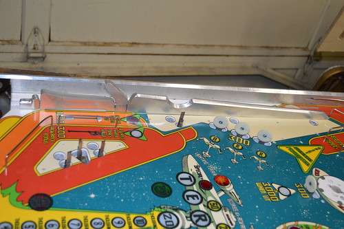
Now I think you guys can see why I went with a "bladed" side rail... the two complement each other quite well.

Another angle with another surprise feature of the PF...

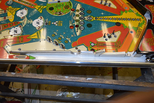
Several months ago; I contacted Cliffy at PassionForPinball.com and asked him to do a custom inlane switch protector for this project. He graciously agreed. For inlane switch; he cut me a custom Enterprise switch protector which I cnced a place for it making it "level" with the PF wood/clear.

Here's the mandatory money shot for the kids at home:


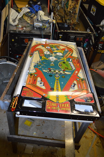
Starting to look like a Pinball machine now; isn't it?

Offline zitt

  • Trade Count: (0)
  • ****
  • Forum Posts:
Re: Star Trek: The Mirror Universe pinball
« Reply #110 on: January 20, 2014, 07:00:10 PM »
A couple of weeks ago; I did a pretty big PinballLife.com order... part of which was those awesome new Aluminum Flipper bats:
.

Today; I executed the strategy for these bats. First went ahead and powdercoated them black... then a second clearcoat powder with the metal flake seen on the apron. Once I had the bat powdercoated; I laser etched a jig on the tormac laser cutter at techshop.  This etch allowed me to position the bats in such a way that they ready to get their treatment:
.

The Bats go into the Laser cutter to get their dagger etches:
.

I hear the audience screaming for a money shot... who am I to argue?
.

And that concludes my weekend update for you guys... Next up I'm thinking it's time to start the wiring harnesses for the boards, switches, Etc. I wanted to get the LED boards in place so I can figure out how to route the harnesses under the PF. Not sure how long this will take... so bear with me.

Offline oldskool1969

  • Trade Count: (0)
  • ******
  • High Score Initials:
  • Forum Posts:
  • perth
Re: Star Trek: The Mirror Universe pinball
« Reply #111 on: January 20, 2014, 08:08:54 PM »
 $$(. Pretty sweet and your skills are awesome
If it isn't broke, it isn't pinball.

Offline swinks

  • Trade Count: (+18)
  • ******
  • High Score Initials:
  • Forum Posts:
  • Lake Macquarie, NSW
Re: Star Trek: The Mirror Universe pinball
« Reply #112 on: January 20, 2014, 09:21:26 PM »
great work, thanks for keeping us updated
https://swinks.com.au

for pinball parts (reproduction & mods)
for pinball t-shirts

Offline ktm450

  • Trade Count: (+1)
  • ******
  • High Score Initials:
  • Forum Posts:
  • Geelong, Victoria
Re: Star Trek: The Mirror Universe pinball
« Reply #113 on: January 21, 2014, 08:23:06 PM »
Very cool, love the updates  ^^^

Offline Crashramp

  • Trade Count: (+3)
  • ******
  • High Score Initials:
  • Forum Posts:
  • Albury
Re: Star Trek: The Mirror Universe pinball
« Reply #114 on: January 21, 2014, 08:28:17 PM »
Outstanding!  #*# #*# #*#

Offline pinball god

  • Trade Count: (+1)
  • ******
  • High Score Initials:
  • Forum Posts:
  • Melbourne
  • Metallica is here to stay
Re: Star Trek: The Mirror Universe pinball
« Reply #115 on: January 22, 2014, 10:42:45 PM »
too much for me to process  ^&^. Can't imagine how you dreamt up all these parts let alone the time inputted to make them a reality. Like I said, absolutely mind blowing
Still loving my Metallica Premium

Offline zitt

  • Trade Count: (0)
  • ****
  • Forum Posts:
Re: Star Trek: The Mirror Universe pinball
« Reply #116 on: January 27, 2014, 05:32:32 PM »
I needed to work on the eject mechanism. I carefully measured the standoffs on the original part and engineered an alternate plan since I didn't have the time to replicate the part exactly. Instead I opted to buy some off the shel threaded inserts with nylon sleeves.

For the base which holds the eject bracket; I got a 7/8" threaded #8-32 standoff from Master-Carr.com #91125A210. This piece would be mounted to the top with an #8-32 screw and would provide the rotation point for the eject bracket. To space the arm off the base I went with a 3/8" nylon spacer with 1/4" I.D. and 1/2" O.D #94639A141.

Then goes the bracket arm. For the top of the bracket; I went with a PRess-Fit Drill bushing, 0.25" ID, 0.5" OD @ 3/8" length or #9491A252. I topped it off with two flat washers (think they were 1/4") and star washer and another #8-32 machine screw.

For the plunger arm which goes into the solenoid; I went with a 0.25" tall round spacer with a 1/4" OD and and 8-32 screw thread, #91125A140. The nylon spacer on top was a 1/8" long with 0.25" ID and 0.5" OD.

Here's a picture of the original eject mechanism vs the new one:


Here's the mechanism with the coil and other hardware transferred:


And mounted in the PF:


My only concern is vibration loosening the #8-32 screws holding the threaded inserts in place. As a result; I may end up locktite-ing the screws in place later.

Offline zitt

  • Trade Count: (0)
  • ****
  • Forum Posts:
Re: Star Trek: The Mirror Universe pinball
« Reply #117 on: January 27, 2014, 05:56:46 PM »
With the eject mechanism squared away; time to move on to the Proximity sensors. For those who don't recall; I didn't want switch holes taking away from the art of the playfield. As a result; I wanted to use a Proximity sensor to sense the ball instead of a mechanical switch. I went thru several designs ... none really worked. Settling on the tried and true TDA0161 designed used in modern Williams designs. Mixed in a little of my own circuitry and out came a custom layout which was 80% SMT except the "owner replaceable parts" Basically the diodes and the output transistor remained thru-hole... along with the TDA0161 which remained socketed.

I stenciled on some solder paste and went to work hand assembling 8 PCBs for use on the Playfield switches. All the SMTs were mounted and they went into the skillet for reflow:


I then hand soldered the thru hole components and ran thru a bench test and calibration to make sure they worked prior to install.

I was trying to figure out how to mount the sensing coils in the Playfield slots (underside); when it dawned on me that I could just mount the PCB over the slots and run the sensing coil on the bottom side of the PCB... pushing the leads down so the coil touched the bottom of the slot. Luckily I had incorporated 3 mounting screw holes in the design so mounting ... so the PCB became the coil mount. :D

I marked the mount holes with a center punch; and proceeded to drill and tap each mount hole for a #6-32 nylon standoff as the light boards were mounted. Here's the PF with the proximity sensors mounted:


And a close up showing a set of PCBs mounted with the coil leads going into the slots:


With the PCBs mounted; I could then transfer the wiring harness from the donor PF to the Mirror Universe. Ofcourse it too had to be mirrored but that was easily accomplished by flipping the harness:


Now the fun of crimping connectors and re-soldering coil/switch terminals begins.
I also need to re-assembly the GI circuits/lamps. The cheapskate in me wants to try an re-use the old GI lamp sockets. However, the do-it-right guy in me; want to order new GI lamps so I won't have to deal with the damn flickering due to warn-out GI lamp sockets. Yes; I know you can solder/hack an old GI Lamp to work... but my experiences has been it doesn't work on every lamp.

Offline swinks

  • Trade Count: (+18)
  • ******
  • High Score Initials:
  • Forum Posts:
  • Lake Macquarie, NSW
Re: Star Trek: The Mirror Universe pinball
« Reply #118 on: January 27, 2014, 06:23:57 PM »
nice progress, looking good.

I have always wanted to use proxy sensors on a custom pin - would you sell some pre-assembled and tested?
https://swinks.com.au

for pinball parts (reproduction & mods)
for pinball t-shirts

Offline zitt

  • Trade Count: (0)
  • ****
  • Forum Posts:
Re: Star Trek: The Mirror Universe pinball
« Reply #119 on: January 27, 2014, 06:30:14 PM »
Let me get finished with this project first... While I tested it on the bench; it hasn't yet be tested in the full machine.
I'd like to know for sure it's ready to go before going that route. Also; keep in mind I only had 10bare PCBs made... so we'd have to get more manufactured before I could build a set.

One thing about the design did concern me... I had driven the switches with 12VDC and saw 9VDC at the pins of the Row/Column when the sensor isn't sensing. This concerns me given it's a 5V MPU. Luckily; My GI is DC ~8V.... so I'm going to drive the Prox Sensors w/ 8VDC... to get ~5V max at the row column pins with inactive.