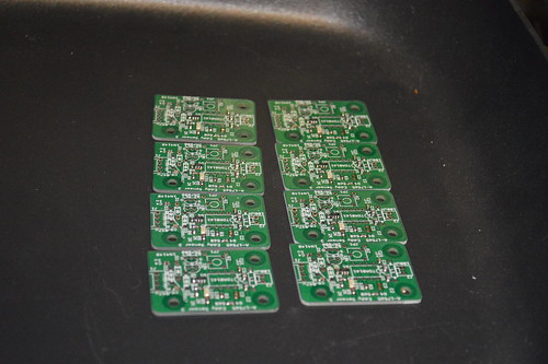
With the eject mechanism squared away; time to move on to the Proximity sensors. For those who don't recall; I didn't want switch holes taking away from the art of the playfield. As a result; I wanted to use a Proximity sensor to sense the ball instead of a mechanical switch. I went thru several designs ... none really worked. Settling on the tried and true TDA0161 designed used in modern Williams designs. Mixed in a little of my own circuitry and out came a custom layout which was 80% SMT except the "owner replaceable parts" Basically the diodes and the output transistor remained thru-hole... along with the TDA0161 which remained socketed.
I stenciled on some solder paste and went to work hand assembling 8 PCBs for use on the Playfield switches. All the SMTs were mounted and they went into the skillet for reflow:

I then hand soldered the thru hole components and ran thru a bench test and calibration to make sure they worked prior to install.
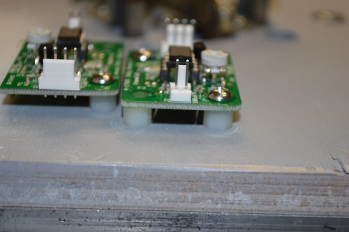
I was trying to figure out how to mount the sensing coils in the Playfield slots (underside); when it dawned on me that I could just mount the PCB over the slots and run the sensing coil on the bottom side of the PCB... pushing the leads down so the coil touched the bottom of the slot. Luckily I had incorporated 3 mounting screw holes in the design so mounting ... so the PCB became the coil mount.

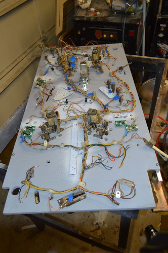
I marked the mount holes with a center punch; and proceeded to drill and tap each mount hole for a #6-32 nylon standoff as the light boards were mounted. Here's the PF with the proximity sensors mounted:

And a close up showing a set of PCBs mounted with the coil leads going into the slots:

With the PCBs mounted; I could then transfer the wiring harness from the donor PF to the Mirror Universe. Ofcourse it too had to be mirrored but that was easily accomplished by flipping the harness:

Now the fun of crimping connectors and re-soldering coil/switch terminals begins.
I also need to re-assembly the GI circuits/lamps. The cheapskate in me wants to try an re-use the old GI lamp sockets. However, the do-it-right guy in me; want to order new GI lamps so I won't have to deal with the damn flickering due to warn-out GI lamp sockets. Yes; I know you can solder/hack an old GI Lamp to work... but my experiences has been it doesn't work on every lamp.