It's was an awesomely mild weekend here in Austin; so I spent quite a bit of time in the garage working on the underside of the Playfield.
Thru the cold snap earlier in the week; I sent an internal goal of wiring the GI circuits/Lamps with color coded wire - A color a night. Rather than wiring each lamp with a bare stapled wire - I point-to-pointed each in it's specific color. IE Green, orange, red, and white. With the GI squared away during the week; I spend this weekend tackling the Hot common of the switch illumination (Blue). I also crimped my fingers swore; as I completed the Inserts wiring.
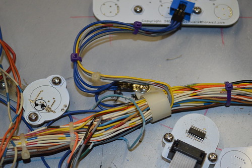
For the top GI connection; the original harness had two blue wires which were soldered to the "Common" of the lamp matrix. Instead I made a custom harness out of some 22gauge blue wire. Each one of these lamp boards had to be wired into that common.
I tinned a piece of raw copper clad (blank circuit board material) and used it as a common tie point for the upper playfield's common hot. Each board was crimped to a length of blue wire and it was soldered to this tie point. The inserts were then crimped and installed on the connectors. Each LED board has a header so it can be uninstalled and fixed if necessary. For the upper playfield; A chain of 22awg blue wire moves between each led board in a circle; so in effect - each board has two 22AWG paths to hot. This should help with redundancy and supply more than enough current flow to lite the leds on the board. In the case of the upper two boards; they have 4pin connectors ... with 2 Anodes and the 2 signal wires.
And yes; for the most part; each LED board has a little Terran Empire logo in copper and/or silkscreen.

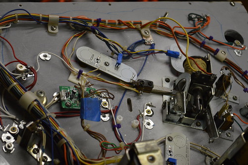
For the middle of the PF; I tapped into the blue wire harness and used a rounded barrel terminal to house the common hot. This common point feed the Klingon LED board as well as the center Enterprise inserts.
2 qty 22AWG blue wires feed the center inserts common point:

I had to cut the tie wraps for the middle of the harness and feed some of the shorter wires between the drop target inserts and the led nacelle boards. With this new route; I had enough slack to make it to the large center insert connector for all signals.
Finally; I added another common hot tie point for the center Xk's inserts:

I'm not real happy with the way this turned out... the wiring harness and connector are in the way of each other. Can't really be helped at this point; but you can still disconnect the board with minimal effort so it's still a win.
At this point; I'm about 80ish-% complete on the bottom side of the PF:
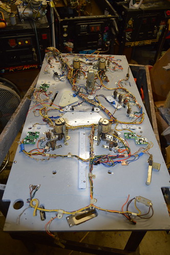
What's left to do on the bottom side?
1) Still need to wire in proximity sensors.
2) Flippers
3) Slingshot switches
4) Drop target assembly
5) Wire GI to nacelle boards; need to double confirm PSU board outputs the polarity I think it does for the GI so I don't hook it backwards.
6) Mount outhole switch and inlane switches.
My only question for you guys; is there typically a suggested method to refurbing the drop target assembly? I already have some new drop targets; but I'm wondering if I should try to source some new springs for assembly. Thoughts?


