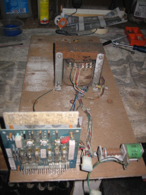
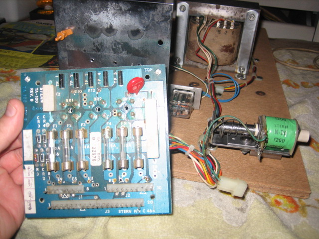
Power Supply & Transformer AssemblyThis covers the Bally power supply boards AS2518-18 and Stern boards from the same era. This is the Stern board out of the Stern Meteor Restore found HERE
http://aussiepinball.com/index.php?topic=1256.0These boards are usually mutilated will all sorts of creative hacks done during the lifetime the machine. Not this one. This is easily the best I've seen in a long time. Suggests that the game was well maintained and repairs were made, rather than the board have fuses of higher values than rated installed. Regardless, I like to rebuild the power boards, components may look to be in good condition, but they may be out of tolerance due to age.
BeforeI didn't test the power supply, I simply rebuild it and upgraded it. Fuses were all of the correct rating - which is a great sign.
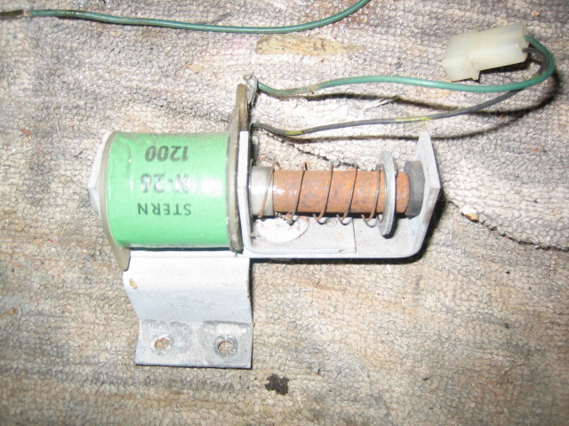
Plunger and assembly looks a bit corroded - No problems there - Ranex to the rescue.
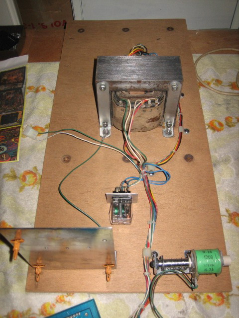
 The Transformer and assembly
I stripped all the parts off the wooden plank and washed them in hot water with nifti. The transformer and credit assembly brackets were polished on the buffer and the plates were cleaned with a wire brush. Screws were submerged in a small tub of Ranex and buffed. The Wood was sanded with 120 grit. Everything was re assembled. All I had to do was rebuild the board !
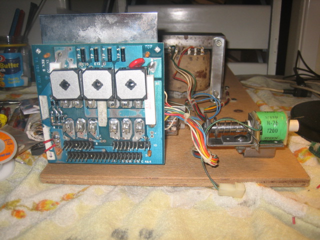
When finished - it should look like this ;
 Rebuild of the Power supply Board
I usually replace everything except the Varistor. I make my own rebuild kits, and I source them from GPE in bulk. I use the upgrade method used by Clay on the Marvin's Guides. The process can take anwhere from 3 - 10 hours depending on the condition of the board. This particular board was clean and very easy to work with. I replace all the parts for reliability and the components are old and may have drifted out of specification / tolerance.
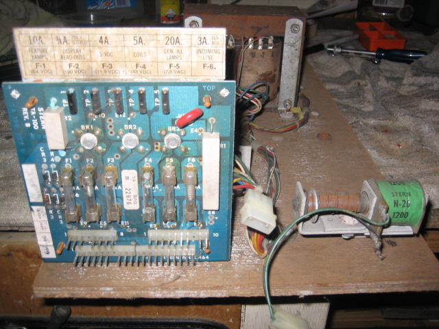
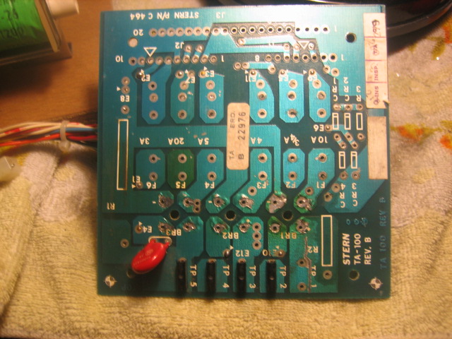
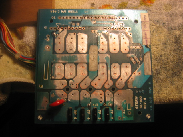
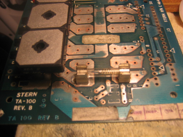
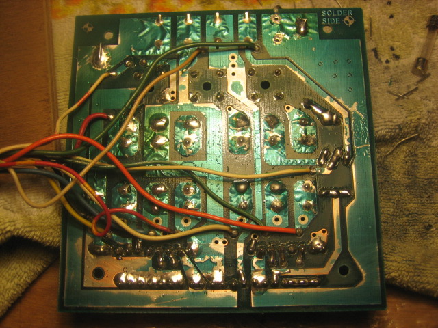
Here's the board before I started ;
All the components are removed, taking care that the small collars that are in each component hole are not accidentally removed. I use a simple method of a solder sucker and a soldering station set at 700 degrees. A quick clean with a toothbrush and Alcohol and the new parts are ready to install. I had to remove the TP1 test point as the metal part was corroded, and the leg of R2 can be used.
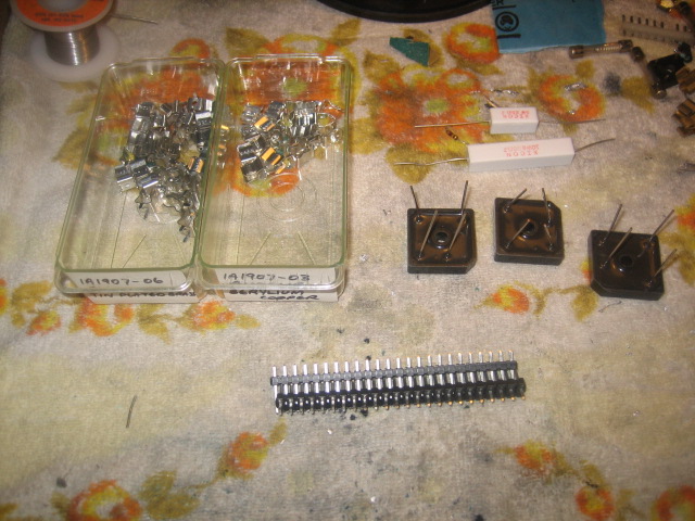
The old parts ;
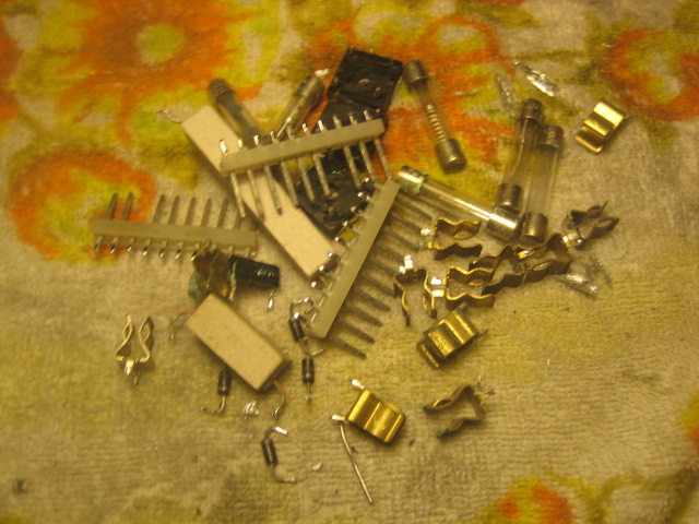
The new parts - except the 100K 1/4 Resistor and 4 X 1N4004 Diodes. I use the Tin plated brass Fuse clips for low current application and the Beryllium copper for 10A and 20A fuses.
 PreparationDon't skip this step !
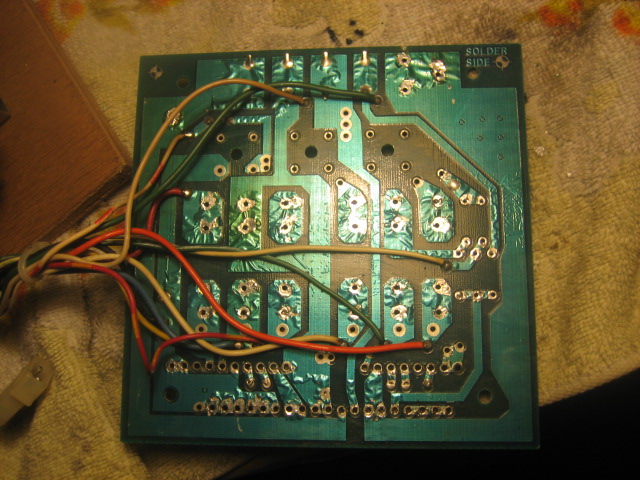
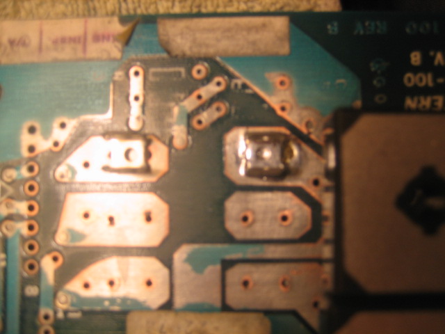
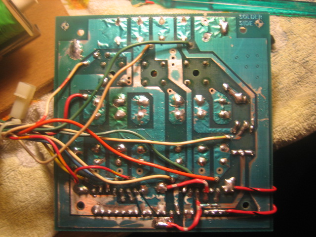
I prefer to sand the board with 360 Grit sandpaper to remove the old solder and to remove the blue sections from the fuse areas. I started doing this a while ago as I noticed corrosion UNDER blue areas, and I could not work out why the solder would not make good contact. The second reason is to increase the surface area that the new fuse clips will be soldered onto. More on that later. I sand the areas where I need to solder right down to the copper - this removes all old solder and flux which would still be present. It will look similar to this ;
 Fuse Clips
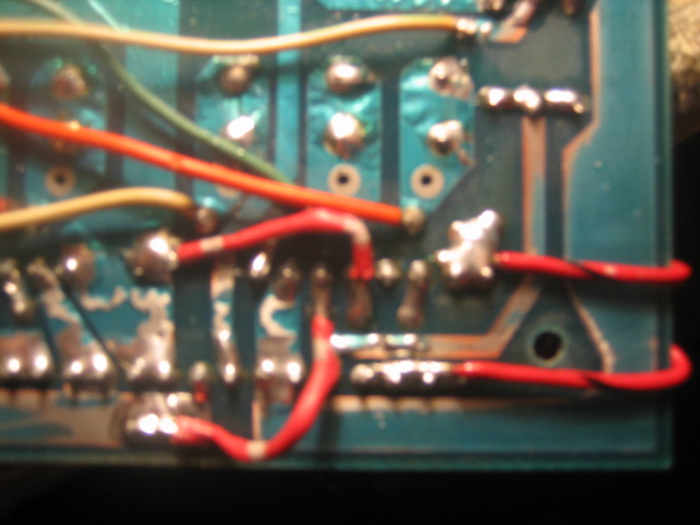
Here's what I do - Insert the new Fuse Clips into place. The picture below shows only the RHS clip soldered. I ensure the clip is pushed flush with the board. Then heat the base of the clip and place the solder on one end, let it flow, and then quickly flow the solder on the other side. The aim is to have the solder almost cover the base - giving it more surface area on the clip.
Once the RHS clip has cooled down, fit a fuse into the soldered clip - the LHS clip is not soldered yet, but the fuse will help ensure that the distance between the two clips is sufficient. Ususally, good quality (buss) clips have a section at one end of the clip that has a lip to ensure the fuse cannot dislodge. If this is not checked, then the fuse will not "clip" into the clip correctly.
 Bridge Rectifiers
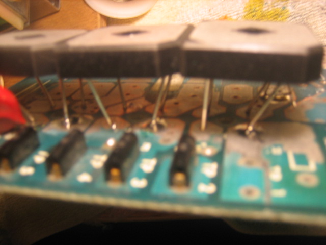
ALWAYS use wire legs, not lugs. These are 400V 35Amp BRs, and you need to be careful fitting these on your boards, as they are much larger than the originals, and they are mounted on the reverse side. The holes in the board need to be free of any solder - the legs are a tight fit. Start with the middle BR, as it's legs will be straight. Then fit the LHS and RHS. The legs need to be bent as per the pictures below. Once they are fitted, solder one topside leg of each BR - because they will move as you work on soldering them in. Once you are happy that they are straight, make sure they are soldered in on the TOP and BOTTOM of the board. Leave the BR's legs as long as possible for airflow. I have not installed the heatsinks yet - as I have to order them, but they are easy to install later - as long as the legs are LONG !
 Connectors, diodes and resistors
The easiest part, and best to leave until after the BRs and Fuse Clips are done. Simply trim the .156 connector, trim the Keyed pin, and solder into place. Start at one end, and then check that the connector is flush, solder the other end and check again. Then just do all the pins. Repeat for all the other connectors. Install the diodes and the resistors and you are done ! Ensure the large resistors have space underneath them for air flow. It should look like this ;
 Mods and Upgrades
I have been using Clay's guides for years, and I simply follow his directions from the Marvin's guides
http://www.pinrepair.com/bally/index1.htm#psClay deserves a lot of credit for saving many machine and boards over the years.
However - He makes it look so easy ! Here's my typical upgrade results ;
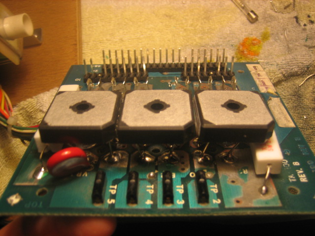
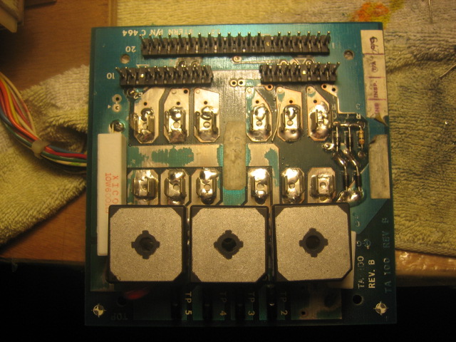
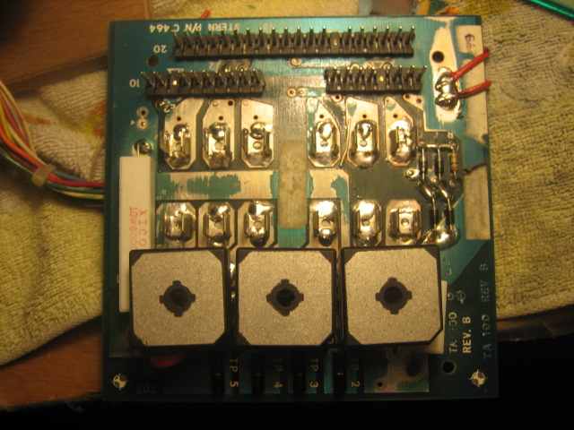 Finished Board !
The board is done and fitted to the Transformer assembly. Next step is to install new fuses and test in the machine
Typically, these voltages should be seen in attract mode
TP1 - 6.4 VDC
TP2 - 195 VDC
TP3 - 13.5 VDC
TP4 - 7.5 VAC
TP5 - 47 VDC
These will be 10 - 15% over these value with no load.
Installed into the game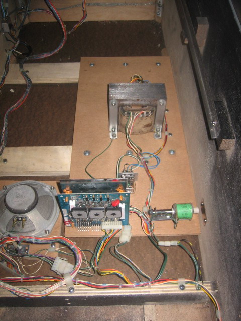
The final step is to replace the factory pins in the connectors (J1, J2 & J3) with Trifuricon pins. Don't skip this step !!
I will start a new post as a Tech guide for any Techie type questions rather than on this restore, as the detail may get lost.


