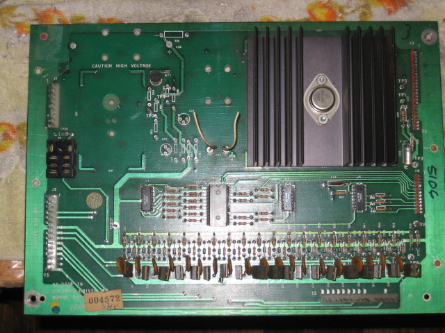
The design of the solenoid Driver board is a curious one. If the HV section develops a short across one of the transistors, then the full voltage appears at the displays. Ever seen the "dots" on a display ? Thats a sign that the display High Voltage is indeed "High Voltage".. Rather than the 175VDC - 190VDC, it has 220VDC applied which causes the displays to "wear out" from the over voltage. From memory, the reason behind this is that if the Transistor shorted and the HV to the displays was fused, then the displays would be protected, but the game would not be earning any takings ! It was assumed that the operator would see the "over bright" displays and then swap the SD over. That never happened !
In addition to the mandatory replacement of the HV Transistors, I made up an additional "kit" that replaces all the HV components. R35 and R31 are usually stressed and quite often burned out. This starts a chain reaction in the circuit and component tolerances are compromised..
C23 and C26are also replaced. C23 should be replaced as it was designed to last 10 years, not 30. On this particular SD, C26 was leaking, literally.
Removing the ComponentsVery easy step. Remove all the components in the HV area. If you are JUST replacing the HV Kit, then remove the transistors only. This involves removing the small heatsink for Q21.
Should look lie this ;
Use 320 Grit Wet/Dry to clean up the solder pads to ensure the fresh solder has the best possible surface area to solder. Clean up using Metho or IsoAlcohol
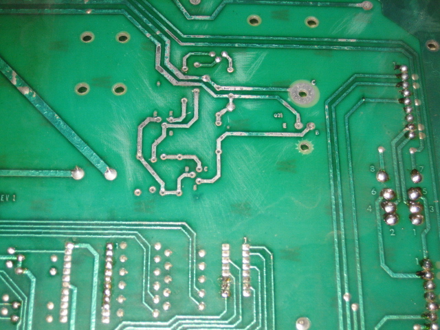
Close up of the rear of the board ;
Close up of the front of the board ;
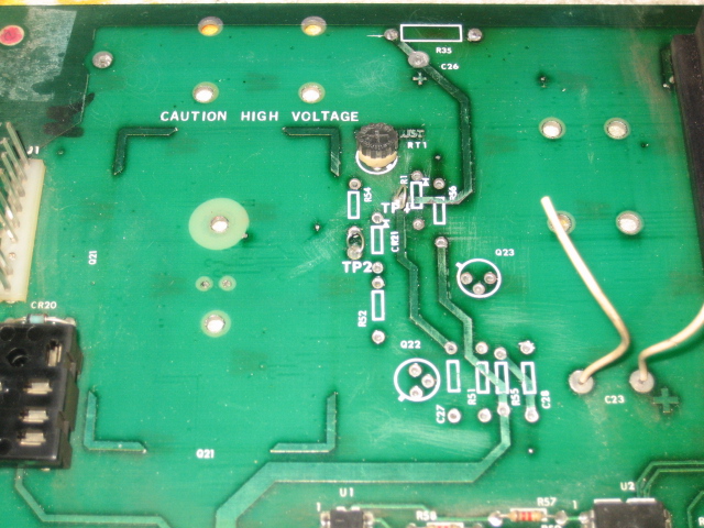
Sand the area clean, and be careful of the solder collars.. I have tested the Adjustment Pot, and it measures fine, so it will be left on the board. Now all is in readiness to install the new components, which I will list and cover in the next update !


