Author Topic: BALLY MPU Kit Assembly Log  (Read 1701 times)

0 Members and 1 Guest are viewing this topic.

Offline Strangeways

  • Pinball Restoration is my passion
  • Administrator
  • Trade Count: (+9)
  • *****
  • High Score Initials:
  • Forum Posts:
  • Melbourne
  • ABN 68 283 634 461
    • Ride The Boney Beast
BALLY MPU Kit Assembly Log
« on: May 30, 2011, 12:02:48 AM »

I have been keenly following Mike's progress on this project and I'm very pleased it has progressed this far, so quickly. So before I start, I'd like to thank Mike for his efforts, and I hope that this guide presents the product in the best possible way. Now I'm like most electronic enthusiasts, I was brought up on Dick Smith and Tandy "do it yourself" electronic kits, so I was really looking forward to building this MPU. I have plenty of experience repairing and rebuilding this MPU board and I've succeeded in bringing back some boards that others would have thrown out. I see those boards as a challenge, but they are TIME CONSUMING to repair. The Altek board has long been an adequate replacement board, but it is always a costly replacement. I have an Altec board that I use - but only to test in my Bally and Stern machines while restoring. I seldom leave them in a game for long periods. I like the idea of the ORIGINAL MPU. That's why I'm VERY keen to see this format almost REPLACE the Altek for Bally and Stern games. Don't get me wrong - there IS a place for Alteks, but it is not cost effective to buy one for the sole purpose of replacing a corroded and fatigued original board. That's where the HOMEPIN board fits in nicely. I have over 20 Bally and Stern Games, and I would use the Altek during the restoration, and then either use an adequate original board, or a Homepin board. I understand circumstances will be different for everyone, but that's where I see this product heading. I fully restored KISS should either have a pristine original MPU, or a Homepin MPU board BEFORE an Altek. Thats because I'm a purist and I like the originality of this board in front of an Altek.

Enough of the dribble  *%*

A pizza delivery man dropped off a package early this week, even though I had not ordered one !  %.%


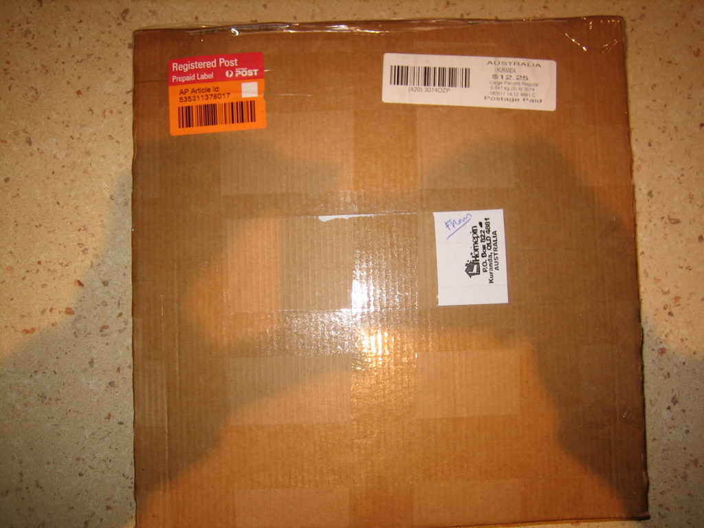
When I opened the package, everything was packed very well and I was surprised that everything fit so easily. Here's the contents of the kit ;


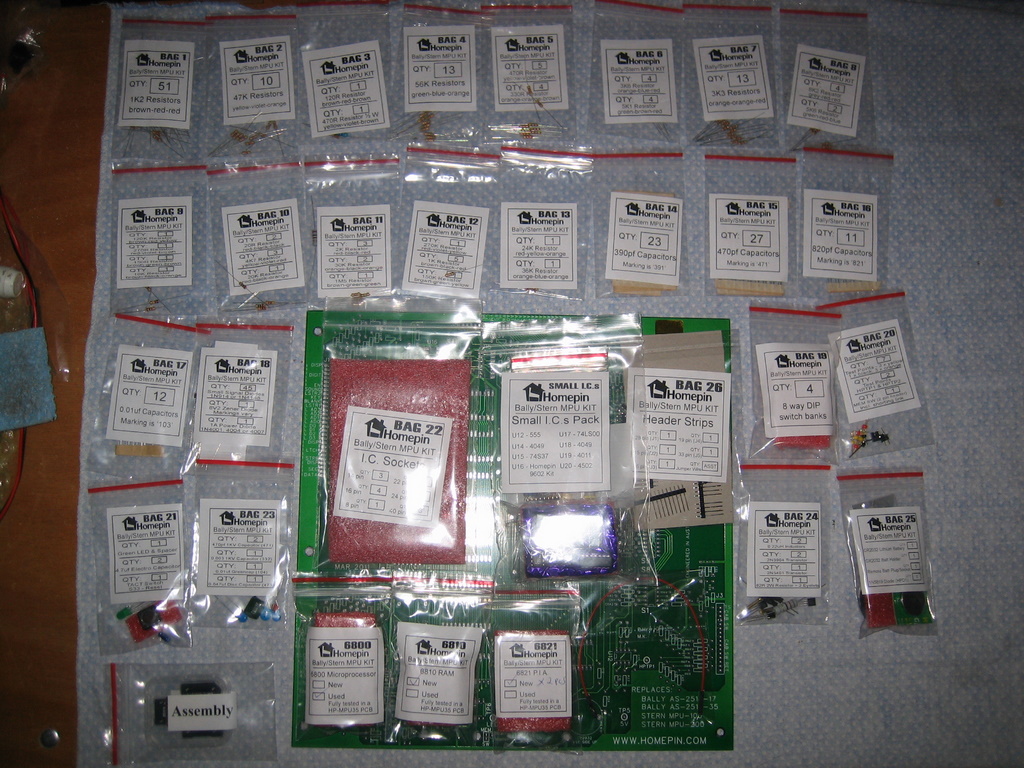
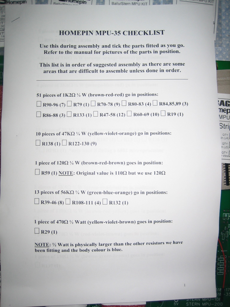
An easy to follow checksheet comes with the kit as well as the instructions on two different SD cards. I didn't look at these throughout the assembly. I'm ther kind of person that does not read instructions. I like to "dive in" and get started. I think the printed instructions will suffice for now ! Notice how all the bags are individually labelled and correspond to each step of the assembly. This is a really nice feature of the assembly process, as you really just need "common sense" to follow it rather than a master's degree in kirchoff's law !

So you basically pick the bag that corresponds with the documentation. Simple enough. As I went through the process, I recorded the time I spent for that given step. This will give me an indication to the amount of time to complete a board.


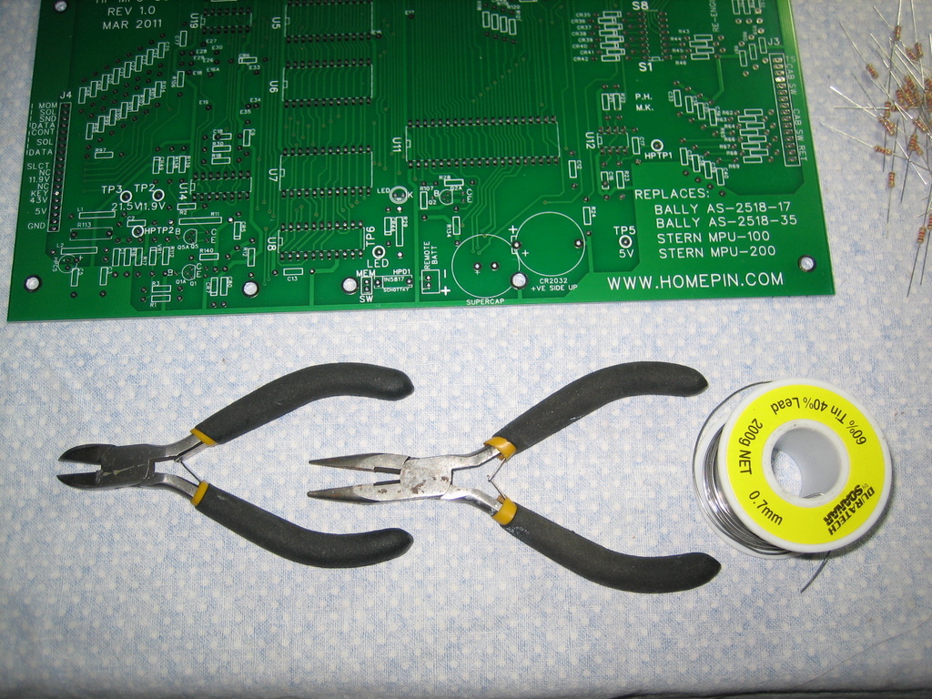
TOOLS - Important to have the right tools for this assembly. I have an "AOYUE 701A" which is a Chinese copy of the Hakko 701. Different is around $800. It is a soldering and desoldering station. I recently bought a new set of tips specifically for this assembly. The Station cost me $300 delivered (around 18 months ago). You only need a soldering station for this job - these can be bought locally at any Dick Smith or Jaycar. Buy a temperature controlled iron with a fine tip.


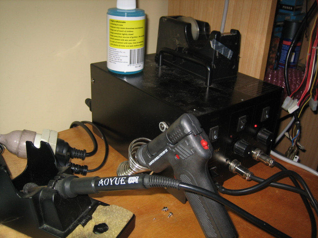
Sidecutters and needle nose pliers. These are "trojan" tools I bought at Jaycar years ago for $8 each. Solder was also bought at Jaycar.


Page 1 - Step 1


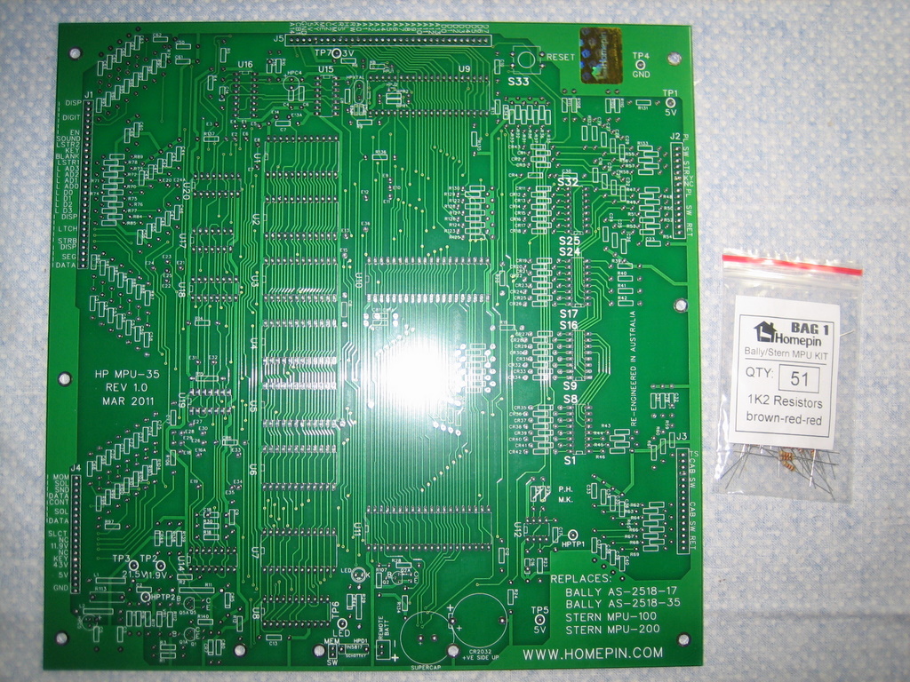
The PCB itself is really well made. There are some observations I will make towards the end of the build that may or may not be part of the next revision of the board - suggestions more than anything else.

"Bag 1" is 51 1.2K Resistors - even the colors are denoted on the notes in the bag. Simple enough. Took me 20 minutes. I solder both sides of the board with a fine point on my soldering iron
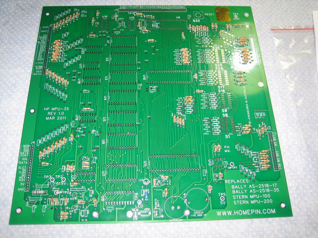


20 minutes later ..


There's around 3 pages of resistors to install. So a quick fast forward ahead to the point when 90% of the resistors are installed on the board. This was simply a case of following the printed guide and checking each stage with the relevant bag of parts. Too easy !


We do the same for the capacitors, diodes, sockets, test points, switches, transistors, inductors and battery housing. I'm at this point as of tonigh. I have not compiled the exact time, but I'm almost there and it looks to ne coming along VERY nicely !


So far - I've really enjoyed the process  ^^^


Observations in the documentation that will need to be updated

Bag 9 has a 10K resistor leftover. This would be R14. I can't find it in the doco.

Page 5 - Microprocessor selection chart for 6800 - Use the jumper HPJ2 - The holes are present, but not much of a solder pad. This may be an issue with connectivity. It looks to be the same for all jumpers. I would like to suggest larger solder pads.

Page 6, the Capacitors are listed, but not where they belong on the board
C14 - 470pF (471)
C15 - 470pF (471)
C16 - 0.1uF Greencap (104)
C18 - 0.047 (473)
C32 - 0.003 (332)

Page 6 - installation of Q1, Q2 and Q5 - The original solder holes are fine - that's how I installed them. The new holes are too small for the transistor legs and there is hardly any solder pad to mount them.

Page 6 - 82 Ohm 2W resistor. The rightmost eyelet is VERY close to CR5's solder pad. I didn't use the eyelets.


I'm REALLY pleased with the build so far, and the above notes on the doco are only a MINOR thing which I'm sure are easy fixes. I must say I've very impressed, and I can't wait to finish the board and install it into my Viking. I'll contime the guide in the next coming days

 ^^^

Aussie Pinball - Proud to be Australia's Premier Pinball Forum

http://www.australianpinballrestorations.com.au/

http://www.rtbb.com.au/catalog/

We carry the largest range of NEW Ramps in Australia

Offline Homepin

  • Trade Count: (+15)
  • ******
  • Forum Posts:
  • Not a business - A Passion!
Re: BALLY MPU Kit Assembly Log
« Reply #1 on: May 30, 2011, 08:18:54 AM »
Glad you are enjoying the build Nino.

Let's look at some of your initial observations, let me first say that all of your points are covered in the electronic manual - it is 56 pages with LOTS of pictures:

Bag 9 has a 10K resistor leftover. This would be R14. I can't find it in the doco.

It is R14, shown & mentioned in manual - ommission on the checklist, will correct.

Page 5 - Microprocessor selection chart for 6800 - Use the jumper HPJ2 - The holes are present, but not much of a solder pad. This may be an issue with connectivity. It looks to be the same for all jumpers. I would like to suggest larger solder pads.

This is actually the way the PCB factory read my files - basically it's a cockup but it is also covered well with pictures in the manual that show how to connect them correctly as are the new transistor pads - the manual suggests ignoring the new holes for the transistors and using the original ones.

Page 6, the Capacitors are listed, but not where they belong on the board
C14 - 470pF (471)
C15 - 470pF (471)
C16 - 0.1uF Greencap (104)
C18 - 0.047 (473)
C32 - 0.003 (332)


Several pages in the manual give this info with lots of pretty pictures.

Page 6 - installation of Q1, Q2 and Q5 - The original solder holes are fine - that's how I installed them. The new holes are too small for the transistor legs and there is hardly any solder pad to mount them.

Yep - as above

Page 6 - 82 Ohm 2W resistor. The rightmost eyelet is VERY close to CR5's solder pad. I didn't use the eyelets.

The right leg of R11 and the top leg of the diode CR5 are actually connected so it doesn't matter if the eyelet touches. Actually it's a pity you didnt use the eyelets because I spent two solid days tracking them down feeling that they add a lot of robustness to the mounting of R11 - never mind.

The advantage to building this board is you can tailor it to be your own. Change things, leave things out, use different micros, memory, battery backup options.

There are about 20 other small things that we have already tweaked for the next run of boards and I'm not telling what they are  <.>.

Remember the checklist is just to help assembly - it is not meant to replace the manual and tha manual is where we concentrated our main efforts. The manual is currently supplied on a T-Flash memory card with an SD card adaptor included - this may change as we tweak things.

You really should at least skim through the manual Nino - there are a lot of subtle things that are mentioned including pitfalls to avoid.

Are you building it for 2716 or 32's?

Replacement Pinball PCBs that remain faithful to the originals

Offline Strangeways

  • Pinball Restoration is my passion
  • Administrator
  • Trade Count: (+9)
  • *****
  • High Score Initials:
  • Forum Posts:
  • Melbourne
  • ABN 68 283 634 461
    • Ride The Boney Beast
Re: BALLY MPU Kit Assembly Log
« Reply #2 on: May 30, 2011, 09:45:06 AM »

Mike - I don't have an SD Card reader on my home PC, so that's why I was referring to the Printed Document throughout the build (and I'm LAZY with this regard). I'll make a point to take the card to work and read it on my laptop.

"The right leg of R11 and the top leg of the diode CR5 are actually connected so it doesn't matter if the eyelet touches. Actually it's a pity you didnt use the eyelets because I spent two solid days tracking them down feeling that they add a lot of robustness to the mounting of R11 - never mind."

No problem Mike, I didn't bother to check that. I'll fit the eyelets tonight. I believe they are a good idea, I was keen to create the build thread last night, so "obvious" things like this didn't occur to me !

I think the checklist is fine to use as a build document for people like me who like to "dive in" and have some experience. The next board I build I will use the manual rather than the checklist, as the additional features are new to me.

I will be jumpering the board for 2732 with Viking ROMs.

I might finish it tonight - see how I go !
Aussie Pinball - Proud to be Australia's Premier Pinball Forum

http://www.australianpinballrestorations.com.au/

http://www.rtbb.com.au/catalog/

We carry the largest range of NEW Ramps in Australia

Offline beaky

  • Trade Count: (+7)
  • ******
  • Forum Posts:
  • Melbourne, Vic
Re: BALLY MPU Kit Assembly Log
« Reply #3 on: May 30, 2011, 10:44:44 AM »
watching this with plenty of interest. your doing a great job Nino.
As an old tech friend of my told me, "when all else fails, read the manual"  :lol
On site pinball repairs in MELBOURNE NTH SUBURBS  : Circuit board repairs and refurbishing Australia wide (via Aust post)

Offline Homepin

  • Trade Count: (+15)
  • ******
  • Forum Posts:
  • Not a business - A Passion!
Re: BALLY MPU Kit Assembly Log
« Reply #4 on: May 30, 2011, 10:49:50 AM »
I am pleased that you are making comments - it will allow me to improve the kit.

I hadn't figured on anyone NOT being able to read an SD card???
In light of that I will put the manual up as a download on my site. It will be there in about 30 minutes.

I have ammended the manual to make mention of the eyelets possibly touching the CR5 - we tried to keep everything in it's orginal factory position (although we did use some artistic licence with a few things) - we do intend shifting a few things around and also makeing some slight adjustments to a few hole sizes - both up and down in size..overall though it does work out fine.

................UPDATE.................

OK, the assembly manual and checklist are now available for download from the MPU page of my site. I have added some words to the checklist just for you Nino - front page changes here:  <.>


« Last Edit: May 30, 2011, 11:28:32 AM by Homepin »
Replacement Pinball PCBs that remain faithful to the originals

Offline ktm450

  • Trade Count: (+1)
  • ******
  • High Score Initials:
  • Forum Posts:
  • Geelong, Victoria
Re: BALLY MPU Kit Assembly Log
« Reply #5 on: May 30, 2011, 02:08:40 PM »
Nice work, I really enjoy that soldering like that, very rewarding when it all works *%*

Offline beaky

  • Trade Count: (+7)
  • ******
  • Forum Posts:
  • Melbourne, Vic
Re: BALLY MPU Kit Assembly Log
« Reply #6 on: May 30, 2011, 02:48:47 PM »
I may end up buying one just for the fun of assembling it.  :lol If only I had the spare $$$.
On site pinball repairs in MELBOURNE NTH SUBURBS  : Circuit board repairs and refurbishing Australia wide (via Aust post)

Offline Strangeways

  • Pinball Restoration is my passion
  • Administrator
  • Trade Count: (+9)
  • *****
  • High Score Initials:
  • Forum Posts:
  • Melbourne
  • ABN 68 283 634 461
    • Ride The Boney Beast
Re: BALLY MPU Kit Assembly Log
« Reply #7 on: May 30, 2011, 03:10:31 PM »
I may end up buying one just for the fun of assembling it.  :lol If only I had the spare $$$.

I recommend buying one just to have one handy. You can burn the 2732 and you are up and running.

Thanks for the updates Mike.
Aussie Pinball - Proud to be Australia's Premier Pinball Forum

http://www.australianpinballrestorations.com.au/

http://www.rtbb.com.au/catalog/

We carry the largest range of NEW Ramps in Australia

Offline Retropin

  • Trade Count: (+4)
  • ******
  • Forum Posts:
Re: BALLY MPU Kit Assembly Log
« Reply #8 on: May 30, 2011, 04:58:14 PM »
LOL- is it the Alltek board that comes with instructions that at the very start say something like...


..."if you are reading this then you have already installed the board and run into trouble"..


I know ONE of the boards i once bought had something like this!

Offline Strangeways

  • Pinball Restoration is my passion
  • Administrator
  • Trade Count: (+9)
  • *****
  • High Score Initials:
  • Forum Posts:
  • Melbourne
  • ABN 68 283 634 461
    • Ride The Boney Beast
Re: BALLY MPU Kit Assembly Log
« Reply #9 on: May 30, 2011, 11:13:01 PM »

Gavin - I think it is the Ni-Wumpf as Ace has a wicked sense of humor.

OK - I've downloaded the manual from the website and read it - and I must say it is VERY WELL written and EASY to follow  ^^^

I used a spare 9602 for this board.

I managed to finish off the board tonight, and I tested it using a 2 X 2732 Bally "Skateball" ROMs that were in my test board. I initially made a big boo boo by breaking one leg of each PIA as I installed them. I simply resoldered them back on and it worked first time - with the jumper installed for 7 flashes. Here's a picture in on my test fixture ;


Tomorrow I will burn a set of Viking ROMs and test it in my game (where this board will reside). For now, I'm very happy with the build !

Aussie Pinball - Proud to be Australia's Premier Pinball Forum

http://www.australianpinballrestorations.com.au/

http://www.rtbb.com.au/catalog/

We carry the largest range of NEW Ramps in Australia

Offline 63wizz

  • Trade Count: (0)
  • ******
  • Forum Posts:
  • Tasmania
    • My Pinball Collection
Re: BALLY MPU Kit Assembly Log
« Reply #10 on: May 31, 2011, 03:47:33 PM »
It looks like a fun project. I hope to get one on the next run. #*#

Ian

Offline Mr Pinbologist

  • Trade Count: (+5)
  • ******
  • High Score Initials:
  • Forum Posts:
  • Wauchope NSW
Re: BALLY MPU Kit Assembly Log
« Reply #11 on: May 31, 2011, 06:02:17 PM »
Lookin good, it DOES look like a fun project   @@*

Too bad i dont need any bally/stern MPU boards at this time.

Offline Strangeways

  • Pinball Restoration is my passion
  • Administrator
  • Trade Count: (+9)
  • *****
  • High Score Initials:
  • Forum Posts:
  • Melbourne
  • ABN 68 283 634 461
    • Ride The Boney Beast
Re: BALLY MPU Kit Assembly Log
« Reply #12 on: June 01, 2011, 12:13:10 AM »

Burnt a set of 2732 ROMs for Viking and it booted without any problems at all. I'll install it into my game and give it a crack tomorrow !

 @@*
Aussie Pinball - Proud to be Australia's Premier Pinball Forum

http://www.australianpinballrestorations.com.au/

http://www.rtbb.com.au/catalog/

We carry the largest range of NEW Ramps in Australia

Offline ajlaird

  • Trade Count: (0)
  • ******
  • Forum Posts:
  • Greensborough, Melbourne
  • Go Ahead, Make My Day
Re: BALLY MPU Kit Assembly Log
« Reply #13 on: June 02, 2011, 07:44:42 AM »
Nothing better than assembling a board and having it work first time!

Offline Strangeways

  • Pinball Restoration is my passion
  • Administrator
  • Trade Count: (+9)
  • *****
  • High Score Initials:
  • Forum Posts:
  • Melbourne
  • ABN 68 283 634 461
    • Ride The Boney Beast
Re: BALLY MPU Kit Assembly Log
« Reply #14 on: June 14, 2011, 09:53:20 AM »

I've tested this board in my Viking for over a week now, and it has been rock solid. Not one single issue. It will now be permanently located in this game, which will be restored shortly - at least I don't have to do any board work !

 ^^^
Aussie Pinball - Proud to be Australia's Premier Pinball Forum

http://www.australianpinballrestorations.com.au/

http://www.rtbb.com.au/catalog/

We carry the largest range of NEW Ramps in Australia