Author Topic: Star Trek: The Mirror Universe pinball  (Read 10846 times)

0 Members and 1 Guest are viewing this topic.

Offline zitt

  • Trade Count: (0)
  • ****
  • Forum Posts:
Re: Star Trek: The Mirror Universe pinball
« Reply #15 on: February 04, 2013, 05:50:46 PM »
I did finish the inserts a couple of weekend ago; but had a puzzle to put together - more on that momentarily.

Here's the Clear Yellow and Green inserts. I didn't bother to photo each version; since I pretty much decided I like the frosted Spiral Galaxy versions.


I didn't need to clear yellow; but I cut them anyway... because I need the smaller peices you'll see next. I think I'm going to use the clear yellow inserts to represent the 3X bonuses.

Observent people noticed there some details peices on the CAD drawing I showed earlier. These detail peices are for the Nacelle graphics in the original playfield. I was always... dissappointed these warp nacelles didn't light up on the original PF. So; I wanted to see if I could change that on The Mirror Universe.

Anyone like Puzzles? If so... have I got some fun for you:

All kinds of colors of the rainbow. And no... I not real fond of puzzles.

I laser cut some plywood in about the size of the nacelle image on the PF. and put together the puzzle of Yellow, Red, Orange to replicate the nacelle. Once I had the 20some odd peices in the correct order I "tooth pick" clamped the pieces tightly together:


and then used some acrylic solvent to glue the pieces using capillary action. I made sure these peices were tight together to ensure a tight bond was formed. I haven't really tried to "Break" these parts; but I've dropped them a couple of times and they haven't shattered.

I made two with the Yellow/Orange/Red/Yellow combo - the identical combo as the PF graphic. Since I had the peices; I went ahead and created a combo which more closely resembles the Enterprise... W/ Red as the main color; orange/yellow/white.

Once I had the pieces welded together with the solvent; I need to make them level. However, I notices that even tho I cut these parts from the same file; their with minor gaps between some of the pieces where they didn't meet. I didn't want to see unfiltered light come from between the acrylic. I pondered; thought about Epoxy w/ some kind of dye... but remembered that I created some crafts with the wife many years ago. It was some plastics stainglass in a bottle. I had pearl white; but couldn't find the Red or Yellow. I tried Michaels... and all they had was some sh1tty martha stewart glass "paint" for $4 a bottle. "Meh" I thought. So I waited until Monday when Hobby Lobby would be open. A lunch trip turned up the exact thing I remembered:
Ruby Red Gallery Glass and the Sunny Yellow. These two oz bottles were like $2.75 a bottle. Using the bottle applicator; I filled the cracks with the appropriate color. I didn't get the Orange- because I wan't sure Pumpkin Orange would match the acrlyic orange. Since red and yellow always border orange; I could use one of the two. I used pearl white for the center "star" on the red insert.

Once I had the cracks filled; I proceeded to attempt to use the orbital sander to help level these inserts; at which one of the yellow inserts went flying into the neather regions of my garage. a quick search didn't turn it up. At that point I went to manually sanding these parts flat.

The result?


And the money shot:


I like the red a lot better than the yellow.

Offline zitt

  • Trade Count: (0)
  • ****
  • Forum Posts:
Re: Star Trek: The Mirror Universe pinball
« Reply #16 on: February 04, 2013, 07:18:12 PM »
I can’t claim originality here... as I remember the XENON machine at a past TPF which had NIXIE tubes instead of the standard VFD displays. I always thought they were cool.
 
Now that I’m designing Star Trek: The Mirror Universe; I’m thinking that I want to put NIXIE displays in the machine instead of stock Bally displays.
 
I’ve been doing some design work; and have come up with the following schematics which use the IN-12A tubes from Russia. They are nearly the same digit height as a stock display and and are relatively inexpensive compared to other tubes.

Just put the finishing touches on the silk screen for the Base board for the Nixie display.
 
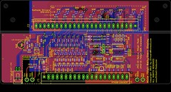
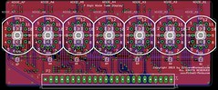
Here’s a image of the boards as they stand today.
Base Board:


Display Board:

 
New features added:
1) The “Right angle” Display board has surface mount LEDs under the tubes; the idea here is that when the display is “active” meaning PlayerX is up... the switched LAMP driver on the side of the display turns on these LEDs causing them to backlight the display ... to help identify which player is active. A Brightness POT on the baseboard controls the brightness.
Opto-Isolated the “lamp” input from +5V logic.
 
2) I added decode logic to support 7digit display ROM hacks:
Update 6 Digit Bally pinballs to 7 digit
where buy D5 =1= D6 causes the 7th digit to become active. U3 & U4 provide this functionality.
Feature is jumper selectable to for native 7digit or Rom-Hack 7digit mode via JP1.
 
3) Clearly labeled Test Points with voltages. Added 80V test point.
 
4) Additional decoupling caps near U1,U2,U3 and well as a bulk cap for 5V.
 
5) Nixie tube display board is at a “right angle” to the base board (like original); but is back set far enough so “front” of IN-12A displays are near same position as the VFD display.
 
6) HV areas “inside” dotted lines. Generous ground planes to help with thermals.
 
7) Same PCB sizes as original.
 
The Schematics are posted here for review... I’ve never designed a display before... so will probably need to do some design tweaks once I get the Tubes in.
http://www.Pinball-Mods.com/blogs/wp-content/uploads/2013/01/Bally7Nixie.pdf
At this time; the design remains my copy-protected property! Once I've proven the design; I'll consider open-sourcing the design for others to build.
 
I went 7digits instead of 6... so they can be used in other machines. I’ll either de-pop NIXIE_A7 or figure out how to make my Bally FW run a 7digit display.

Offline ktm450

  • Trade Count: (+1)
  • ******
  • High Score Initials:
  • Forum Posts:
  • Geelong, Victoria
Re: Star Trek: The Mirror Universe pinball
« Reply #17 on: February 04, 2013, 07:51:35 PM »
Nice work on the inserts, both types look great  ^^^

Offline swinks

  • Trade Count: (+18)
  • ******
  • High Score Initials:
  • Forum Posts:
  • Lake Macquarie, NSW
Re: Star Trek: The Mirror Universe pinball
« Reply #18 on: February 04, 2013, 08:08:16 PM »
very cool zitt, interested to see the displays running, definitely keep us posted.

what is the name of the centre that has all the machinery - interested to learn more what they provide.
https://swinks.com.au

for pinball parts (reproduction & mods)
for pinball t-shirts

Offline zitt

  • Trade Count: (0)
  • ****
  • Forum Posts:
Re: Star Trek: The Mirror Universe pinball
« Reply #19 on: February 04, 2013, 08:36:21 PM »
what is the name of the centre that has all the machinery - interested to learn more what they provide.

Techshop.ws

Offline ajlaird

  • Trade Count: (0)
  • ******
  • Forum Posts:
  • Greensborough, Melbourne
  • Go Ahead, Make My Day
Re: Star Trek: The Mirror Universe pinball
« Reply #20 on: February 04, 2013, 08:44:45 PM »
Some impressive work there!

Offline swinks

  • Trade Count: (+18)
  • ******
  • High Score Initials:
  • Forum Posts:
  • Lake Macquarie, NSW
Re: Star Trek: The Mirror Universe pinball
« Reply #21 on: February 04, 2013, 10:35:11 PM »
what is the name of the centre that has all the machinery - interested to learn more what they provide.

Techshop.ws


cheers
https://swinks.com.au

for pinball parts (reproduction & mods)
for pinball t-shirts

Offline zitt

  • Trade Count: (0)
  • ****
  • Forum Posts:
Re: Star Trek: The Mirror Universe pinball
« Reply #22 on: February 15, 2013, 06:26:07 PM »
Tonight I finished the CNC work on the Playfield as I have a 1pm reservation on the Techshop.ws CNC machines for Saturday. Earlier this week I got some Russian Birch in 4x8 sheet to create the PF on. The veneers/cores look to be dense and high quality which should yield a good looking PF.
 
The CNC simulation yielded this rendering (click for full size image):

 
The simulator says 44minutes of machine time – but I’m guessing it’s gonna be longer than that.
 
With luck by 6pm; I’ll be back at home with a fresh playfield.
 
There are two things missing from this PF at the moment – One is the ball lane and the other is the beveled edges of the kickout hole.

I’m not sure yet how to generate these with the tools I have on hand. I need to learn Cut3d and figure out how to incorporate it into the design. I’m hopeful I can add it later after the PF is already CNCed or do some of the work by hand.

Offline swinks

  • Trade Count: (+18)
  • ******
  • High Score Initials:
  • Forum Posts:
  • Lake Macquarie, NSW
Re: Star Trek: The Mirror Universe pinball
« Reply #23 on: February 15, 2013, 09:30:25 PM »
It is possible to do it later on but it is important to say have 4 reference holes in the underside of the playfield so when you come back at a later stage you machine these 4 reference holes mirrored in say a bolted down piece of MDF. Then place 4 dowels in these reference holes and then slide and lock in the pf over these dowel into it's reference holes and bolt this down.

With the pf zero'd in do a air cut above the playfield as you would to stuff it up this late in the game and check your location for the 3D v cut and slowly drop the z down until you are done.

I have done this alot when I needed to machine both sides of things but before you go to do your first stage this weekend add 4 x reference dowel holes preferably in each corner.

Hot that helps

going well  ^^^
https://swinks.com.au

for pinball parts (reproduction & mods)
for pinball t-shirts

Offline zitt

  • Trade Count: (0)
  • ****
  • Forum Posts:
Re: Star Trek: The Mirror Universe pinball
« Reply #24 on: February 19, 2013, 11:42:39 AM »
<Sigh>
This weekend was suppose to be the weekend for real progress; sadly – it didn’t happened.
On Friday; I went to techshop to check on file readiness and water jet a unique piece for the Playfield.

Turned out all the work I’d done (6hrs or more) in the Trial version of Cut2D wasn’t usable in the production version Techshop had. Those a-holes think it’s cute to prevent files created in the trial version from working in the production version unless you spent 500 on the full version. OFcourse the Trial version only outputs from their trial library so I couldn’t export tool paths. I recovered; but I spent a lot of late night hours rebuilding the CNC files. I understand a company wanting to protect their IP – but this is just well – going too far.

I kept my Saturday reservation time - as I worked OT to get the files repaired... When I got to techshop; I realized the didn't stock a full line of Collets for the Shopbot. They only stock 1/4" and 1/2" collets and they don't provide a drill collet for drill bits. I needed a 3/8" ER25 collet and a drill holder for the PF. I don't blame them really - they clearly stated as such in their SBU for the shopbot. I mis-read it. This puts the Pinball table on hold until I get an 3/16" and a 3/8" ER25 collet for the machine. I proably also need to get a v-cut bit and/or a ball nose bit to do the kickout hole and ball lane.

Now onto the unique piece I was to water jet. I built the file in CorelDraw. Let’s just say CorelDraw is absolute crap when it comes to outputting DXF files. When I bring it into FlowPath to generate the waterjet files... the parts have in-exact curves and broken lines. I have to repair it in  FlowPath which takes about an hour. When I take it to the waterjet; the part some how grew by 1.2x ... not that I caught it at the time. So; 40 in aluminum and 40 dollars in machine time is down the drain.  I’ve recreated the design in a real cad program and we’ll see about cutting it in a few days when I get more material.

After about 4 weeks; my 12A Nixie tubes arrived from Russia. First thing I noticed is that the numbers are upside down to what I thought the proper orientation was. To make matters worse the Library that I dled for the Nixie tubes was incorrect and the pin numbering was off. This renders one of the two circuit boards for the nixie displays invalid. I’ve fixed the pinout in the library and have re-laid out the display board. Plan on submitting it to BatchPCB tonight. I think the PCBs are running behind because of Chinese holidays... so not sure if I’ll actually get the PCBs in time for TPF’13. I gambled by committing the PCB before I had the tubes... and lost that bet.

I did get my ColorDMD for the STNG installed last Thursday... so at least that went well.

Hoping your weekend was better,
John

Offline swinks

  • Trade Count: (+18)
  • ******
  • High Score Initials:
  • Forum Posts:
  • Lake Macquarie, NSW
Re: Star Trek: The Mirror Universe pinball
« Reply #25 on: February 19, 2013, 07:32:57 PM »
still sounds good and the good thing is you have worked out the solutions to the problems, look forward to seeing the work that you have done.
https://swinks.com.au

for pinball parts (reproduction & mods)
for pinball t-shirts

Offline zitt

  • Trade Count: (0)
  • ****
  • Forum Posts:
Re: Star Trek: The Mirror Universe pinball
« Reply #26 on: February 21, 2013, 06:42:04 PM »
Tonight was a good night. I figured out the toolchain to take the ball lane and kickout hole from Sketchup into the CAD software.
 
I used Sketchup 8 to create the files (easiest 3D software I can barely use). Once I had the file created in Sketchup; I exported the model to a 3D model in DAE format. Then I used Meshlab 1.3.0 to convert the .dae into an .stl which could be read by Cut3D.  Here’s the models as the look in MeshLab:

 
Once I had the tool paths figured out; I imported the .v3d file into Cut2D and aligned it in the file. The simulation shows me this:

 
This should allow me to cut, drill, and carve the PF in one "session" on the shopbot. Simulation told me 1hr 7minutes... but I'm skeptical. :D
 
I couldn’t figure out why the Ball lane path is “etching” the non-lane wood. I tried a couple of things but they didn’t seem to make it better – only worse. So; I plan on leaving the 1/4” ball mill a little higher when it’s cut to try and avoid the etches.
 
Collets are on order via Fleabay since Monday... I’m going to order the 1/4” ball mill before I got to bed (I hope).

Offline swinks

  • Trade Count: (+18)
  • ******
  • High Score Initials:
  • Forum Posts:
  • Lake Macquarie, NSW
Re: Star Trek: The Mirror Universe pinball
« Reply #27 on: February 21, 2013, 07:09:30 PM »
looks good, do you know the cut speed (mm per minute) as I would of thought just under a hour once everything is up and running is ok.

are you going to spot screw holes etc in the understand as then some locator holes will be beneficial.


Thankyou for taking the time to post the info as it is interesting.  ^^^
https://swinks.com.au

for pinball parts (reproduction & mods)
for pinball t-shirts

Offline zitt

  • Trade Count: (0)
  • ****
  • Forum Posts:
Re: Star Trek: The Mirror Universe pinball
« Reply #28 on: February 21, 2013, 07:19:35 PM »
looks good, do you know the cut speed (mm per minute) as I would of thought just under a hour once everything is up and running is ok.

No. I'm not sure of the cut speed on the shopbot and the birch plywood. I think the longest time is the mill thru for the inserts and outline. Next is proably the ball lane.
The longest time is proably going to be tool swaps and re-zeroing the tool to the PFs.

Quote
are you going to spot screw holes etc in the understand as then some locator holes will be beneficial.

Lost me - your phrasing through me off.
Are you asking if I am drilling screw holes in the PF? If so; yes. The 1hr time includes drilling 7 different screw hole sizes. Some thru the board. Some @0.3" inches.
Basically; I'm drilling all the holes I should need for the top side; including ball guide rail holes.

As for the bottom; I'm not drilling anything except what is drilled from the top side.

Offline swinks

  • Trade Count: (+18)
  • ******
  • High Score Initials:
  • Forum Posts:
  • Lake Macquarie, NSW
Re: Star Trek: The Mirror Universe pinball
« Reply #29 on: February 21, 2013, 09:12:56 PM »
looks good, do you know the cut speed (mm per minute) as I would of thought just under a hour once everything is up and running is ok.

No. I'm not sure of the cut speed on the shopbot and the birch plywood. I think the longest time is the mill thru for the inserts and outline. Next is proably the ball lane.
The longest time is proably going to be tool swaps and re-zeroing the tool to the PFs.

Quote
are you going to spot screw holes etc in the understand as then some locator holes will be beneficial.

Lost me - your phrasing through me off.
Are you asking if I am drilling screw holes in the PF? If so; yes. The 1hr time includes drilling 7 different screw hole sizes. Some thru the board. Some @0.3" inches.
Basically; I'm drilling all the holes I should need for the top side; including ball guide rail holes.

As for the bottom; I'm not drilling anything except what is drilled from the top side.


yes that is what I meant with SPOTTING the screw holes

with the cut speed, it all depends on the combination of machine and router and cutter but you should easily  achieve 1000mm per minute but could go up to 2000 to 6000mm per minute. You probably have been taught this but ensure that you slow the cut speed for tight curves / corners otherwise the machine will over size the cut due to momentum going one direction and then radically another. Also on any multi-depth cuts, offset the initial cuts but have the final cut - cut the size you want and it cleans up the cut lines of the previous depth cuts = just looks nice. Hope I haven't confused you.
https://swinks.com.au

for pinball parts (reproduction & mods)
for pinball t-shirts