Author Topic: Star Trek: The Mirror Universe pinball  (Read 10845 times)

0 Members and 1 Guest are viewing this topic.

Offline goodolddays

  • Trade Count: (0)
  • ******
  • Forum Posts:
  • Riverstone NSW
Re: Star Trek: The Mirror Universe pinball
« Reply #30 on: February 25, 2013, 11:49:15 AM »
What an awesome project you have going on there .  $$(

Sure is a major undertaking .

I will be keenly watching your progress on this one.

Your insert design looks excellent too  ^^^
I need more room ! and more $$$

Offline zitt

  • Trade Count: (0)
  • ****
  • Forum Posts:
Re: Star Trek: The Mirror Universe pinball
« Reply #31 on: February 28, 2013, 06:43:06 PM »
A while back; I put the breaks on further work on the Plastics. The reason I stated was that I was working on a plan to knock your socks off. Tonight is the moment I reveal the plan and work that has been done.

When I realized my art skils were not up to the task... I decided to consult a professional. I approched a well known Star Trek graphic novel artist with the project; and he agreed to do the work on commission. It wasn’t cheap; but I decide to do it because I was spending so much effort to make this a one-of-a-kind original; that it would just stupid (in my mind) to leave the plastics art to an armature artist like me.

The schedule we settled on was for him to deliver me Pen and Ink drawings electronically by this past weekend to enable me some time to create the plastics prior to TPF'2013. Monday he delivered the drawings.

Oh; and BTW: I'm retaining all rights to the art for now... as I have worked out final rights with the artist. No one is allowed to reproduce these for any reason.


Now that I had the ink files; It was time to do some photoshop work on it ... I decided I wanted to color the drawings rather than hire another professional; thereby spending more bank.


TBH; I'm very pleased with the results.
Gordon did an EXCELLENT job giving me the baseline for the art don't you think?

I may do some more work on Sulu as he looks off with the teeth.

Comments / Suggestions?

Now I need to send him the plans/Ideas for the BackGlass. First; I have to scan the existing backglass and measure the critical parameters. So; now is your chance to provide ideas for said backglass; I want to get him something by Friday.
 
On other fronts, the Nixie tube boards and digikey parts came in today... I’m only missing the backlight leds ... once I have them; I’ll be ready to start assembly.

Offline Retropin

  • Trade Count: (+4)
  • ******
  • Forum Posts:
Re: Star Trek: The Mirror Universe pinball
« Reply #32 on: February 28, 2013, 06:56:40 PM »
PM sent

Offline ktm450

  • Trade Count: (+1)
  • ******
  • High Score Initials:
  • Forum Posts:
  • Geelong, Victoria
Re: Star Trek: The Mirror Universe pinball
« Reply #33 on: February 28, 2013, 07:56:23 PM »
Nice work on the plastics  *%*

Offline zitt

  • Trade Count: (0)
  • ****
  • Forum Posts:
Re: Star Trek: The Mirror Universe pinball
« Reply #34 on: March 23, 2013, 06:42:09 PM »
The Mirror project was put on hold for the last three weeks... First due to the SxSw Intel LANfest I was hosting... and then Texas Pinball Festival this past weekend. Now that I had the Pins back in the Garage'cade; I've refocused my effort on the Nixie Pinball Display.

I hand assembled the base and display boards and soldered them together.

I didn't want to commit the untested display to my Bally Star Trek... so I needed to figure out how to facilitate debug.

First problem was how to supply 190VDC to the HV section. Some googling found me some 555 timer circuits which would run off of a 9V.
Had most of the parts except a 250V 4.7uf cap and a pot. A trip to Frys solved that problem.
A bread board and an ATX power supply and I had a 190V psu. The ATX supply provides +5v to the display and +12V to the 190V psu's input.

Here’s a picture of the prototype 555 190V Nixie supply:


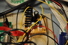
Initial debug turned up a dumb assembly mistake..– I swapped U1 & U2 despite the clear labels on the silkscreen.
 
I hardwired the display inputs to only lite digit 1 and display an 8 (1000b). 8 because it's the digit which uses the most current given the largest area. This will allow me to verify the anode current before committing to a final anode resistor. To "latch" the 8 digit; I used my RatShack Logic pulser to toggle the LE pin.
 
I was able to empirically  calculate the Anode resistor using the built-in test point and pot. 21.4k... now I just need to find some 22k 603 resistors to make it work. 21.4k gives me 2.5mA of anode current which is typical for the NH-12A tubes I’m using.
 
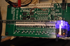
Here’s the top view of the display boards:


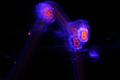
And the money shot for the backlite display:

 
I decided early on that I wanted the backlite to be purple rather than some other color because I thought it’d contrast nicely against the orange digits.
You can see the testpoint and Anode pot right below the Nixie tube. Obviously; these will be de-poped for “production” boards.
 
Here’s a picture I just thought was cool. A result of playing with camera shutter times:

 
With the resistor calculated; I need to focus on creating a Display tester so I can run the display thru all the digits and functions.

Offline zitt

  • Trade Count: (0)
  • ****
  • Forum Posts:
Re: Star Trek: The Mirror Universe pinball
« Reply #35 on: March 24, 2013, 02:32:06 PM »
Someone mentioned using an Arduino to drive the pinball display as a tester.
Initially I dismissed it because I had an “activewire” microcontroller board here which was collecting dust.
 
Turns out the activewire board only has drivers for WinXP... none for Win7.
While at Frys today; I saw they had some Arduino usb devices for fairly cheap. I ended up getting a Nano which had 14DIO pins – barely enough to drive the display.
 
A few hours later; I had a working Pinball Display tester:
http://youtu.be/kz3ikA82iH8
 
I’ll publish the code later; but thought you’d guys want to see the display functional asap.
Tests all the digits and the BLANK functionality which is between the 9 and the 0.
 
Next step is to desolder the current display PCB and build a fully populated display based on the latest PCBs. Once I have a fully populated display; I can test all the digits and the 7digit emulation capability.

Offline zitt

  • Trade Count: (0)
  • ****
  • Forum Posts:
Re: Star Trek: The Mirror Universe pinball
« Reply #36 on: March 25, 2013, 04:16:29 PM »
Today; I verified the Nixie Pinball Display as completely functional.
I populated all the nixies on a FabB Display board; installed all the backlit LEDs and ran the full test against it.
All the digits work; and the emulation works as expected. Setting A5 = A6 = 1 emulates the 7th digit.
I haven’t checked for the 7th digit in non-emulation mode; but expect it to be low hanging fruit.

I did find that the 300k resistors along with the 110V “bias” voltage via Zener was necessary. Without the bias; some digits would see ghosting in non-active digits. By driving the anodes and Kathodes to 110V when not in use; the digits won’t flicker.

Here’s a video of all the digits working:
http://youtu.be/7Eys2KxI20g

Next step is to finalize FabB of the base and display boards while the changes are still fresh in my mind.

Offline Steevsee

  • Trade Count: (+1)
  • ******
  • High Score Initials:
  • Forum Posts:
  • Brisbane
Re: Star Trek: The Mirror Universe pinball
« Reply #37 on: March 25, 2013, 05:04:29 PM »
Those displays look amazing.

Thanks for sharing.

Offline swinks

  • Trade Count: (+18)
  • ******
  • High Score Initials:
  • Forum Posts:
  • Lake Macquarie, NSW
Re: Star Trek: The Mirror Universe pinball
« Reply #38 on: March 26, 2013, 07:21:46 PM »
very cool displays  ^^^
https://swinks.com.au

for pinball parts (reproduction & mods)
for pinball t-shirts

Offline elkor-alish

  • Trade Count: (0)
  • ******
  • Forum Posts:
  • Perth
Re: Star Trek: The Mirror Universe pinball
« Reply #39 on: April 04, 2013, 01:42:20 AM »
Displays are great!

I was already quite interested in this project but now I'm impressed and wanting more.
I can't wait to see what you come up with for the rest of the machine.
Pins: The Getaway, TotAN, WH2O, Pinball Magic, Banzai Run, Flintstones, Judge Dredd, Lord of the Rings LE, Metallica LE, Iron Man VE, The Walking Dead LE, Star Trek The Next Generation.

Offline zitt

  • Trade Count: (0)
  • ****
  • Forum Posts:
Re: Star Trek: The Mirror Universe pinball
« Reply #40 on: April 05, 2013, 05:13:09 PM »
While I try to figure out what is wrong with the jumper selectable native 7 or 7 digit emulation for the nixie tube display; I've been working on the two of the plastics I had forgotten about.

I forgot about the orbit/arch plastics which are at the top of the PF. Might as well bang them out before I try to make the plastics. I scanned them into my computer a while ago; and took this time to clean them up and vectorize them. I tried to color match them against the new plastics shown previously - reusing colors and the like.

Additionally; I put some extras on the plastics - namely an Klingon D7 Cruiser, the ISS Enterprise, and a star field. I got the Enterprise from the promo plastic which I scanned in and cleaned up.

The result:


Any other suggestions?

Offline zitt

  • Trade Count: (0)
  • ****
  • Forum Posts:
Re: Star Trek: The Mirror Universe pinball
« Reply #41 on: April 09, 2013, 01:34:33 PM »
More debug this wkend seems to point to the 4555 1to4 decoder circuit.
I pulled the tristate buffer (u4) and solder bridged the outputs of the 1to4 decode straight to the transistors thru a 9.1k resistor.
The display does the same thing without U4.
 
This points to U3 (cd4555) being the culprit.
Now; given I’ve already verified 7 digit emulation with the arduino which doesn’t work in the machine; seems to be a clue.
 
I’m leaning toward the output of the MPU being TTL compatible; but not CMOS compatible. I don’t think the signal to the displays is meeting CMOS high requirements for digits 5&6. According to my mpu schematics; the digit enables are driven directly by the output of a 6821 PIA. 
 
So; next step is going to be to wire in an oscope to see what D5’s levels are.
Then figure out how to solve if hypothesis proven.

This pretty much sums it up:

 
PeakToPeak; my displays (digit enables) are only getting 1.6V for a high. Well below the cmos “good” for a 1. This is measured at R44 and R43 closest to the connector on stock displays.
 
This is the reason why my Nixie design isn’t working. I can design around this with either a transistor or some other translation logic; just not sure why the value is so low.
I see why it works on stock displays as all we need is for the high to be > ~0.7V to turn on the digit enable transistors in the original design.
 
Just need to confirm with other pins / people that they see similar results. I only have the one Bally Star Trek; no other era pins.
By confirming other pins; we can determine if this is a design change is warranted.

Offline zitt

  • Trade Count: (0)
  • ****
  • Forum Posts:
Re: Star Trek: The Mirror Universe pinball
« Reply #42 on: April 11, 2013, 02:40:58 PM »
I did some "dead bug" rework to the existing display; basically epoxing two SMT 2N3904s to the top side of U3. I cut some traces and soldered a 20K ohm pull up between VCC and the collector of the transistors. Emitters were tied to ground. Bases were connected to the series resistors currently present in the schematic.


The goal here is to work out the kinks in the design so they can be incorporated into a FAB B board and be relatively confident the design will work out of the box.

Because the BJTs are single transistor inverters; I needed to rewire the input to U3. I wanted to reuse the existing CD4555B chip already present to keep the design simular. Turns out that by swaping A & B inputs vs the schematic; the following boolean logic become obvious:
U3A Q1 = !B*A = D5
U3A Q2 = B*!A = D6
U3A Q0 = !B*!A = D7

Remember that when the MPU is driving A5 or A6 high; the BJTs invert that to be an active low. So the boolean math makes it logical.

The result (finally):
Click here for YouTube movie

Here are some pictures of the display installed in my Bally Star Trek machine:


Known issues:

Digits are too light when running in multiplexed mode (in a real machine); plan to drop the anode resistor to ~2.7k from 22k to brighten the digits. Not a good idea for non-pinball machines which aren't multiplexing the digit enables; but should be fine for more machines.

Need to "fix" the native 7 vs emulated 7 digit jumper selector given the need to re-invert D7 in native mode.

Offline zitt

  • Trade Count: (0)
  • ****
  • Forum Posts:
Re: Star Trek: The Mirror Universe pinball
« Reply #43 on: April 12, 2013, 03:57:35 PM »
Updated schematics are posted here:
http://www.Pinball-Mods.com/blogs/wp-content/uploads/2013/04/Bally7NixieFabB.pdf

Fab B changes:
  • Changes around D[5..7] (solution for A5 & A6 digits not lite-ing):
    • reworked for transistor inverters with pullups.
    • U3A rewired to enable proper output with inverted signals.
    • U3A always enabled  ( !E tied to ground ).
    • U4 I5 & I6 pull from Q1 & Q2 outputs instead of main connector so that cmos levels are observed at input of U4.
    • D7’s resistor moved to base of Q20 and reduced resistance given below.
    • D7’s non-emulated mode drives D2 which is now a SCHOTTKY diode so that lower Vf(D2) doesn’t impact ability to drive Q20 directly.
    • Additional Boolean math notes around U3A decode logic.

  • As observed in Nixie newgroup (among others); Added R70 and R71 to bases of Q6 and Q5 to help protect cmos logic in the event of a shorted MPS-A42.
  • Reduced VR1 from 110V zener to 91V Zener to keep “standby” voltage rail lower than Nixie striking voltages.
  • Changed R62 to 1% 30 ohm resistor to enable LED current measurement via ohms law.
  • Added J5 to R62 to enable pads for LED current setpoint measurements.
  • Collector / Anode resistors reduced from 22K to 2.2k to enable brighter digits in multiplex mode.
  • Stuffed anode/kathode standby resistors. Was empty, is 300k.
  • Changed TP4 testpoint. Was 80V is 90V.

Please let me know if you see anything of concern.

Offline zitt

  • Trade Count: (0)
  • ****
  • Forum Posts:
Re: Star Trek: The Mirror Universe pinball
« Reply #44 on: April 15, 2013, 05:06:38 PM »
This weekend; between income tax sessions; I worked on the PF Apron... I scanned the original into the computer:


As you can see; some TX tax labels, scratches, and some minor rusting makes the apron less than ideal for a project like this.

I've decided I want to replace the logos and text... along with proably changing the base coat to black. Here's my inital revision:


I'm just not sure what I want to do with the two triangular pieces. I've kinda already done the Enterprise on the arches. The imperal sword is already present in the center graphic on the apron... and I also have a plan for something else later in the project.

I thought about doing a mirror Kirk in one of the peices; but that would cost more for the artist to do.

Anyone got any suggestions?