I can’t claim originality here... as I remember the XENON machine at a past TPF which had NIXIE tubes instead of the standard VFD displays. I always thought they were cool.
Now that I’m designing Star Trek: The Mirror Universe; I’m thinking that I want to put NIXIE displays in the machine instead of stock Bally displays.
I’ve been doing some design work; and have come up with the following schematics which use the IN-12A tubes from Russia. They are nearly the same digit height as a stock display and and are relatively inexpensive compared to other tubes.
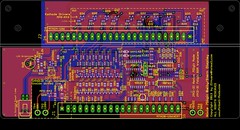
Just put the finishing touches on the silk screen for the Base board for the Nixie display.
Here’s a image of the boards as they stand today.
Base Board:

Display Board:

New features added:
1) The “Right angle” Display board has surface mount LEDs under the tubes; the idea here is that when the display is “active” meaning PlayerX is up... the switched LAMP driver on the side of the display turns on these LEDs causing them to backlight the display ... to help identify which player is active. A Brightness POT on the baseboard controls the brightness.
Opto-Isolated the “lamp” input from +5V logic.
2) I added decode logic to support 7digit display ROM hacks:
Update 6 Digit Bally pinballs to 7 digitwhere buy D5 =1= D6 causes the 7th digit to become active. U3 & U4 provide this functionality.
Feature is jumper selectable to for native 7digit or Rom-Hack 7digit mode via JP1.
3) Clearly labeled Test Points with voltages. Added 80V test point.
4) Additional decoupling caps near U1,U2,U3 and well as a bulk cap for 5V.
5) Nixie tube display board is at a “right angle” to the base board (like original); but is back set far enough so “front” of IN-12A displays are near same position as the VFD display.
6) HV areas “inside” dotted lines. Generous ground planes to help with thermals.
7) Same PCB sizes as original.
The Schematics are posted here for review... I’ve never designed a display before... so will probably need to do some design tweaks once I get the Tubes in.
http://www.Pinball-Mods.com/blogs/wp-content/uploads/2013/01/Bally7Nixie.pdfAt this time; the design remains my copy-protected property! Once I've proven the design; I'll consider open-sourcing the design for others to build.
I went 7digits instead of 6... so they can be used in other machines. I’ll either de-pop NIXIE_A7 or figure out how to make my Bally FW run a 7digit display.