More debug this wkend seems to point to the 4555 1to4 decoder circuit.
I pulled the tristate buffer (u4) and solder bridged the outputs of the 1to4 decode straight to the transistors thru a 9.1k resistor.
The display does the same thing without U4.
This points to U3 (cd4555) being the culprit.
Now; given I’ve already verified 7 digit emulation with the arduino which doesn’t work in the machine; seems to be a clue.
I’m leaning toward the output of the MPU being TTL compatible; but not CMOS compatible. I don’t think the signal to the displays is meeting CMOS high requirements for digits 5&6. According to my mpu schematics; the digit enables are driven directly by the output of a 6821 PIA.
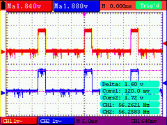
So; next step is going to be to wire in an oscope to see what D5’s levels are.
Then figure out how to solve if hypothesis proven.
This pretty much sums it up:

PeakToPeak; my displays (digit enables) are only getting 1.6V for a high. Well below the cmos “good” for a 1. This is measured at R44 and R43 closest to the connector on stock displays.
This is the reason why my Nixie design isn’t working. I can design around this with either a transistor or some other translation logic; just not sure why the value is so low.
I see why it works on stock displays as all we need is for the high to be > ~0.7V to turn on the digit enable transistors in the original design.
Just need to confirm with other pins / people that they see similar results. I only have the one Bally Star Trek; no other era pins.
By confirming other pins; we can determine if this is a design change is warranted.