Thank you sir!
In between stenciling; I waited for the LED test boards to come on a slowboat from china... I received them early last week. In short; I wanted to do some insert testing with some LEDs to find the "optimal" LED current using my inserts from earlier in the build. I didn't want the inserts to blind the player... but I also wanted to make them look right. As a result; I used the following circuit to vary the current thru the LED:

Basically the single 2n3904 transistor is operating in constant current mode; R2 is empty and the current is measured via the emitter resistor at R8. This particular board was designed to have two uses.
1) Enable "current" test early on...
2) Then after current is known; remove the active circuitry and simply populate the resistors R2 and R4.
Three of these boards would be used to lite under the dual lane inserts. For the LEDs; I went with 0.5W LEDs from Kingbright. the AA3535 series. I went with high power so that I could keep the currents low but still get plenty of photons from the LEDs. This was recommended by a friend in the "know" and I really appreciate his advice.
For the test boards; I went with smart prototypes out of china because they allowed me to order White silkscreen. The white silkscreen will help reflect and stray photons back toward the insert.
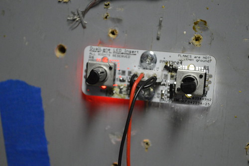
Here's the board installed under the test playfield. It mounts with two wood screws; and allows the pots to be adjusted.

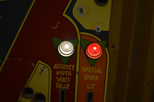
Here's how the board looks from the top w/o the laser cut inserts:

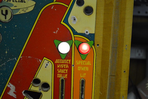
Here's what I think the inserts should look like during play:

With this the measured currents were as follows:
Neutral White: 36.1mA ~= 41.2ohm 1/4W at 5V supply
Red: 24.07mA ~= 86.6ohm 1/4W at 5V supply
Given these are 150mA peak current LEDs; I'm not operating them anywhere near their peak currents. It should help prolog the life and keep them running cool.