Author Topic: Williams / Bally WPC Driver Board Upgrade  (Read 13080 times)

0 Members and 2 Guests are viewing this topic.

Offline Strangeways

  • Pinball Restoration is my passion
  • Administrator
  • Trade Count: (+9)
  • *****
  • High Score Initials:
  • Forum Posts:
  • Melbourne
  • ABN 68 283 634 461
    • Ride The Boney Beast
Williams / Bally WPC Driver Board Upgrade
« on: May 13, 2011, 10:30:11 AM »

WPC Driver Board Upgrades

These are mandatory upgrades that SHOULD be done to any WPC machines. It is a relatively simple job if you have the correct tools. I do this to EVERY machine that needs to be worked on. Why do we need to do this upgrade ? Mainly because of the infamous "reset" on WPC machines - more to do with the combination of BR2 and C5 - the +5V. If this voltage fluctuates, so does the reliability of the game. Most of this procedure is covered in Clay's guides, but with my "guide" I have provided progress pictures. I replace all the Bridge Rectifiers and Capacitors.

The parts you need are simply ;

Bridge Rectifier - 400V 35A Wire legs, or 600V 35A Wire Legs
Capacitor - 15,000 mfd 25 Volt

Both are available locally from our Sponsors

http://www.rtbb.com.au/catalog/product_info.php?products_id=544
http://www.rtbb.com.au/catalog/product_info.php?products_id=918

If not in stock, GPE in the USA will have them, but support the local guys !

Before we start

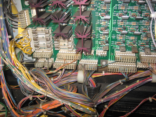
Removing the Driver board involves one key process - LABEL all connectors to the board - Either place a tag on the cable, or write directly on the connector. This will make it a lot easier to install when done ! Take note of the connectors - do any of them look burnt or hacked ? Check the bottom left hand corner - J120 and J121 - These are GI connectors and are almost ALWAYS toasted. This particular board is in excellent condition, so this is what you want to see ! The reason you need to take note is because you will have to replace the connectors, and it is easy to do that while the board is out to do the upgrades.

Here's the GI connectors - Not a good example of what to look for as this board is very good !


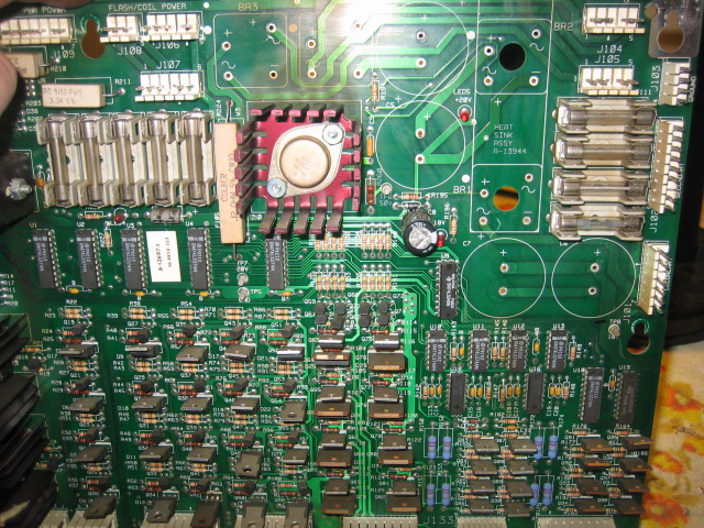
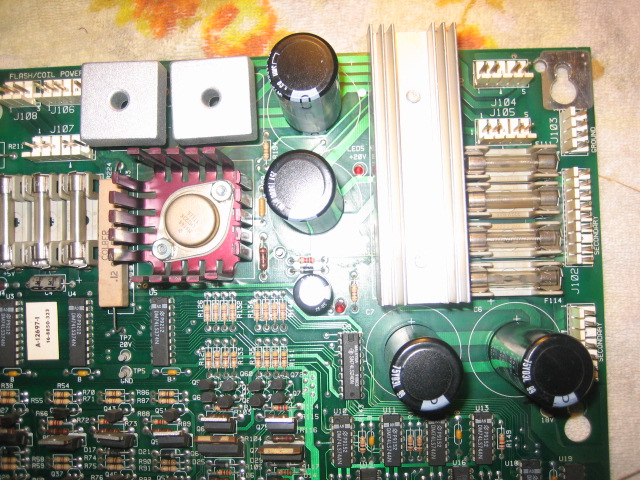
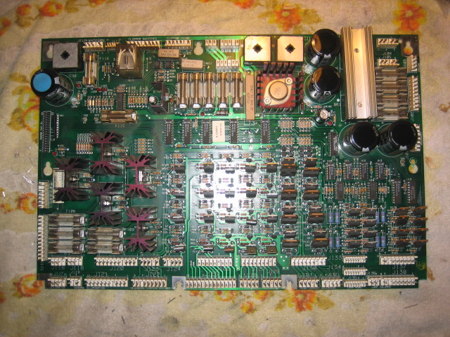
This is the Driver board once removed from the game !


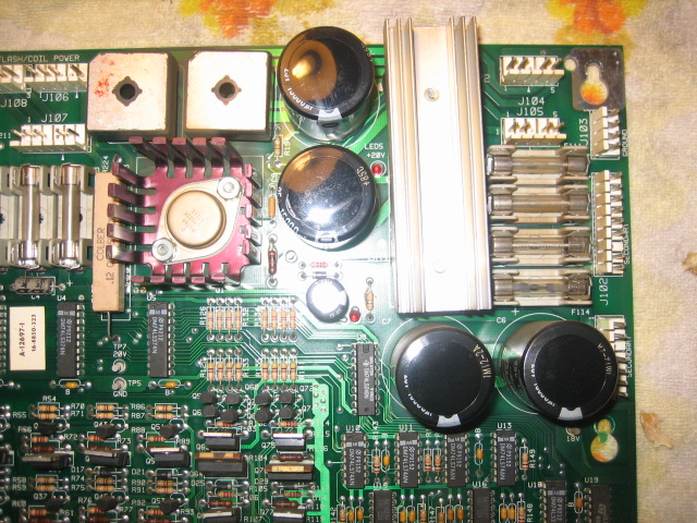
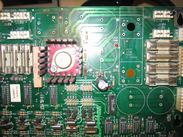
The main culprits - BR1, BR2, BR3, BR4, C11 and C5.


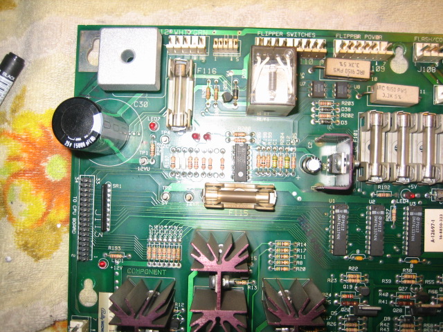
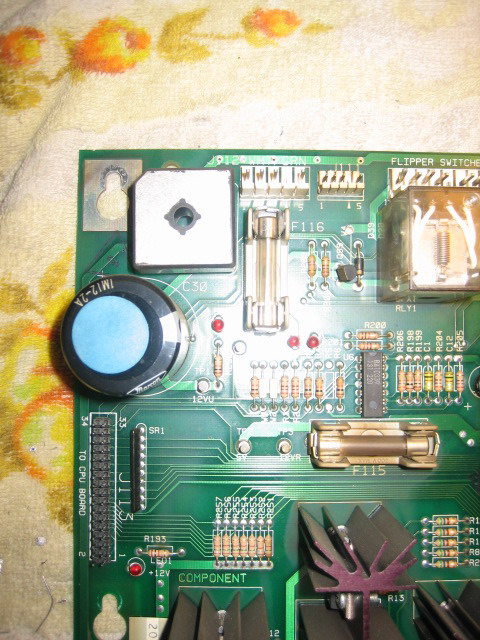
BR5 and C30


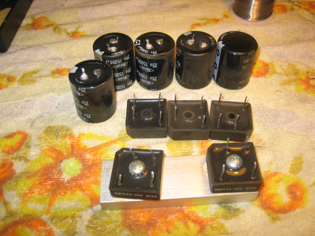
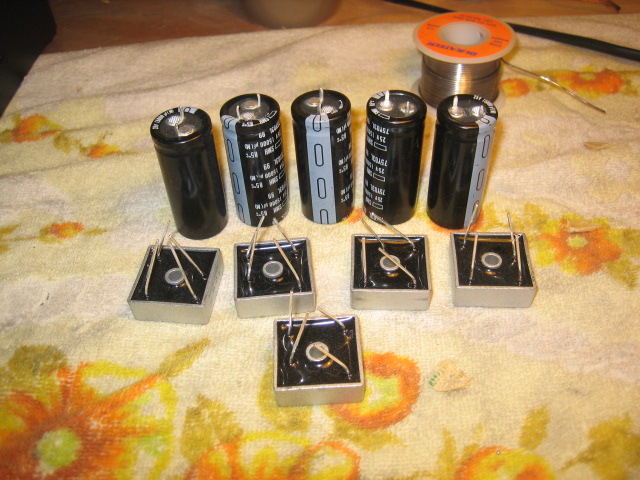
These 5 capacitors and 5 Bridge Rectifiers will be removed and replaced. I USED to use a standard soldering station and solder "sucker" - But this time around, I will be using my Desoldering station.


So this is where I get to test out my Aoyue 701. Removing the Caps and Bridge rectifiers is always a bit of a challenge, as the legs on the Caps are not the expected wire legs, they are more like lugs and they often remove the collar that is the conductor between one side of the board with the other. Sometimes, after completing these upgrades, some voltages may not be present. The Marvin's guide adds jumpers for this very reason, and I've always used them in the past.

I've preheated my desoldering gun, and I've used a little solder for the tip of the gun. The BRs were removed in around a minute per BR ! VERY easy - "stuff all" effort. They simply "fell off" the board once I have done the last of the four legs ! The Caps could not be removed with the desoldering gun - there needs to be a continuous heat applied to each leg. So I used the solder pencil. I placed a fresh "Ball" of solder on each leg and heated one leg up, then gently pulled the leg a little - moved to the opposite leg and did the same. so effectively, I heated up each leg and SLOWLY extracted the capacitor. Took time - but as I removed each Cap, I checked for the copper "collar" - none present - so I dropped a bit of solder on the pads of each removed Cap and used the desoldering gun to "clean up" the hole. This technique worked well - and I had all 5 caps and BRs out in around 15 minutes.


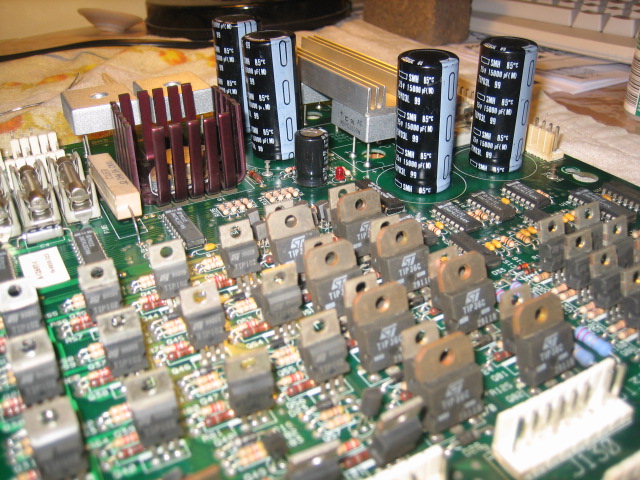
The old ;


The new ;


Here's some pictures of the board with the Caps and BRs removed. Very clean job (this time)


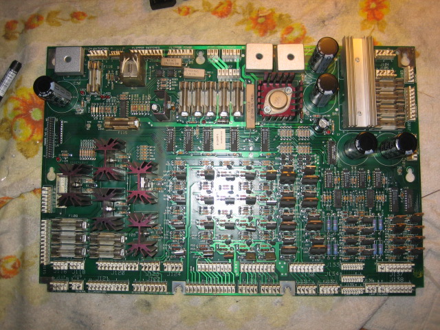
To install the new parts - start with the BRs. Make sure they are installed correctly. Now the really good thing about using a Desoldering Gun, is that the solder pads are clean and the holes have no solder - so when you resolder, the solder can pass through the hole and flow through the collar to the other side of the board. Leave plenty of room in between the BR and the board. Just in case when you solder - the solder does not make a good connection on BOTH SIDES of the board - this is important - especially if the collar was damaged (or any tracks), when the old parts were removed. Now check that the solder is on both sides of the board. If now - now is the time to use the space between the board and the BR to drop some solder on the parts side.

Now install the Caps - make sure they are pushed in all the way.

Should look something like this


Jumpers - I didn't really need them, but I've install some anyway on the main culprits. I mark them out with a permanent marker before taking the parts out. The aim is to ensure that the tracks on the parts side of the board are not severed IF the collars were damaged during removal. So what you do is check the tracks on the parts side while the caps and BRs are removed, and draw a line from the Caps two solder pads to their next component on the solder side. This is where the jumpers will be installed. They are usually connected to the corresponding BR.


Here's an example
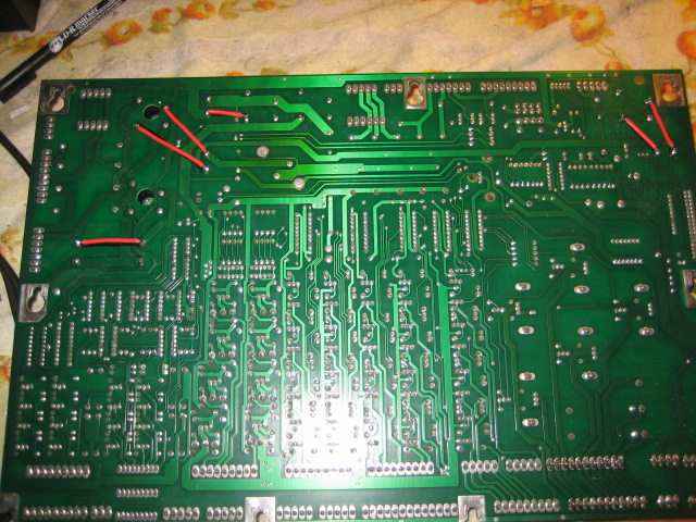


Hard to explain, but it is always advantageous to install the jumpers.

Now that I've used the Desoldering Station for this task - I'll NEVER go back ! While the board is out - Check the GI connectors J120 and J121. Reflow the solder - regardless of whether they look "good" !


 :D
Aussie Pinball - Proud to be Australia's Premier Pinball Forum

http://www.australianpinballrestorations.com.au/

http://www.rtbb.com.au/catalog/

We carry the largest range of NEW Ramps in Australia

Offline pinnies4me

  • Administrator
  • Trade Count: (+5)
  • *****
  • High Score Initials:
  • Forum Posts:
  • Victoria
Re: Williams / Bally WPC Driver Board Upgrade
« Reply #1 on: May 13, 2011, 10:49:11 AM »
Nice step by step guide mate, I might give my WPC games a look over and do this if they weren't done earlier.
“If you wanna escape, go up to a pinball machine. There’s a magic button on the front that takes you to a world under the glass and makes the the rest of the universe disappear.”

Offline ktm450

  • Trade Count: (+1)
  • ******
  • High Score Initials:
  • Forum Posts:
  • Geelong, Victoria
Re: Williams / Bally WPC Driver Board Upgrade
« Reply #2 on: May 15, 2011, 12:34:51 AM »
Nice work Nino, I used to not worry about the jumpers, as I figured I could get a good joint through the board, but a few years down the track after the bridge rectifiers heat up and cool down many times I have had cold solder joints, giving me game resets when both flippers are pushed at the same time, adding the jumpers at this point fixed the resets, so I always do them for BR2 and C5 now

Offline beaky

  • Trade Count: (+7)
  • ******
  • Forum Posts:
  • Melbourne, Vic
Re: Williams / Bally WPC Driver Board Upgrade
« Reply #3 on: May 15, 2011, 12:50:00 AM »
great guide there Nino.
I was just wondering do you use any heat sink compound between the two bridges and the heat sink?
I always use heat sink compound on any thing that bolts to a heat sink. It may not be necessary here but I thought I would ask.  ^^^
 
On site pinball repairs in MELBOURNE NTH SUBURBS  : Circuit board repairs and refurbishing Australia wide (via Aust post)

Offline Mr Pinbologist

  • Trade Count: (+5)
  • ******
  • High Score Initials:
  • Forum Posts:
  • Wauchope NSW
Re: Williams / Bally WPC Driver Board Upgrade
« Reply #4 on: May 15, 2011, 10:15:02 AM »
great guide there Nino.
I was just wondering do you use any heat sink compound between the two bridges and the heat sink?
I always use heat sink compound on any thing that bolts to a heat sink. It may not be necessary here but I thought I would ask.  ^^^
 

Same, i always use some heatsink compound anything that bolts to a heatsink too. I did some work on a driver board for a TZ just a couple of days ago and replaced all the bridges, and the two bridges on the heatsink had the white compound on them, so i cleaned it up and put new heatsink compound on when putting it back together.

Offline Homepin

  • Trade Count: (+15)
  • ******
  • Forum Posts:
  • Not a business - A Passion!
Re: Williams / Bally WPC Driver Board Upgrade
« Reply #5 on: May 15, 2011, 10:29:50 AM »
I agree, let's face it, if something has a heatsink bolted or clipped to it - it is there to disperse heat. Heatsink compound aids in the thermal transfer from the device to the heatsink so I believe it should always be used.
Replacement Pinball PCBs that remain faithful to the originals

Offline FreePlay

  • Trade Count: (0)
  • ****
  • Forum Posts:
  • Lewisham, Sydney
Re: Williams / Bally WPC Driver Board Upgrade
« Reply #6 on: May 15, 2011, 10:43:17 AM »
I know everyone does it ( including me) but is it really necessary to replace the bridge rectifiers?

Offline Strangeways

  • Pinball Restoration is my passion
  • Administrator
  • Trade Count: (+9)
  • *****
  • High Score Initials:
  • Forum Posts:
  • Melbourne
  • ABN 68 283 634 461
    • Ride The Boney Beast
Re: Williams / Bally WPC Driver Board Upgrade
« Reply #7 on: May 15, 2011, 11:39:52 AM »
great guide there Nino.
I was just wondering do you use any heat sink compound between the two bridges and the heat sink?
I always use heat sink compound on any thing that bolts to a heat sink. It may not be necessary here but I thought I would ask.  ^^^
 

Yes Andrew, I use heaksink compound wherever a heat sink is used.

I know everyone does it ( including me) but is it really necessary to replace the bridge rectifiers?


You don't have to, but while the board is out of the game, it is best to upgrade the all the parts. Capacitors are usually good for 10 years, BRs should be fine for longer.
Aussie Pinball - Proud to be Australia's Premier Pinball Forum

http://www.australianpinballrestorations.com.au/

http://www.rtbb.com.au/catalog/

We carry the largest range of NEW Ramps in Australia

Offline carnut

  • Trade Count: (0)
  • ***
  • Forum Posts:
Re: Williams / Bally WPC Driver Board Upgrade
« Reply #8 on: September 09, 2011, 02:01:57 PM »
bravo.this is exactly what has happened to mine.
this forum rocks!
nicely posted.

Offline johnwartjr

  • Trade Count: (0)
  • ******
  • Forum Posts:
  • Columbus, Indiana USA
  • It's ALIVEEEEEE!
    • My Home Gameroom . com
Re: Williams / Bally WPC Driver Board Upgrade
« Reply #9 on: November 18, 2011, 05:18:30 PM »
A few comments after reading through this...

I find J101 and J102 are common reset culprits.. as much, if not more than BR2 and C5.

I find C4 needs replacing as often as C5, if not more often - and it's cheap!

I've gone from replacing everything to trying to do more in depth troubleshooting and replacing only what actually needs replacing. While caps have a limited shelf life, I've got plenty that are 15+ years old in pins still working as well as they did on day #1.

I've had a lot of rework come across my bench from people who meant well, and tried to repair a reset problem by shotgunning parts, and now they have 3-4 problems including ripped up traces, parts installed backwards, or the shotgunning didn't fix the problem (because the reset problem wasn't BR2/C5) and then they go off on other parts of the boards.

Some of my best deals on boards have been from people who went Rottendog and unloaded their perfectly serviceable original boards for a pittance.

If you don't know what you're doing, send the boards to someone who does.

If you think you know what you're doing, but aren't sure, find an old junk board to practice on.

Don't just destroy a $300 PCB when you could've had it fixed for 1/3rd of that :)

Offline robm

  • Trade Count: (+1)
  • ******
  • Forum Posts:
  • Townsville
Re: Williams / Bally WPC Driver Board Upgrade
« Reply #10 on: November 18, 2011, 06:18:30 PM »
Have to agree with JWjr in that i've had a few reset issues fixed by replacing the header pins of J101 J102.....after i pulled the board out a few times scratching my head.

Offline Strangeways

  • Pinball Restoration is my passion
  • Administrator
  • Trade Count: (+9)
  • *****
  • High Score Initials:
  • Forum Posts:
  • Melbourne
  • ABN 68 283 634 461
    • Ride The Boney Beast
Re: Williams / Bally WPC Driver Board Upgrade
« Reply #11 on: November 18, 2011, 07:37:02 PM »

There's a number of ways of attending to reset issues on Power Driver boards, but my theory applies to ANY driver board. Certainly I don't replace all the components for the sake of doing so (and no one is suggesting that), but I work on the fact that Electrolytic capacitors have a limited life span. The dielectric deteriorates over time which can result in a high leakage current, or the electrolyte will eventually dry away. All I'm doing it ensuring that the machine that has the driver board, will have a trouble free operation.

I've followed this procedure on over 50 boards, and never had a reported problem with resets. Having said that, I've never replaced J101 or J102. I replace J120 and J121 on every single board except one.

On Bally SS Driver boards, I won't even repair them until C23 is replaced. I've seen a couple of them have leakage all over the boards.

Replacing the capacitors, bridge rectifiers and J120 & J121 costs around $50 - $55. So it might not be affordable or applicable to everyone. But so far - not one of these games has ever reproduced the reset issue. For an extra $5 - replace J101 and J102 - sounds good to me !

Aussie Pinball - Proud to be Australia's Premier Pinball Forum

http://www.australianpinballrestorations.com.au/

http://www.rtbb.com.au/catalog/

We carry the largest range of NEW Ramps in Australia

Offline beaky

  • Trade Count: (+7)
  • ******
  • Forum Posts:
  • Melbourne, Vic
Re: Williams / Bally WPC Driver Board Upgrade
« Reply #12 on: November 19, 2011, 02:21:07 AM »
When a board is sent to me for low voltage problems I always replace every Electro cap and bridge.
Out of every five of these boards I do I find at least 2 that have a faulty C4 capacitor. ( I test every cap with a cap meter that i pull out just to see how bad they are)
C4 is a 100uf capacitor and i often find them to be down between 40 to 60 Uf. You can also bet that if C4 on the driver board is crook then C31 on the MPU board will also be stuffed.

I also change J114, J115, and all headers for the G.I.s

My opinion is if you are going to pull the board out and replace a cap and bridge then you may as well do a major service. some of the components may not need replacing yet but it will save you on future hassles.

In most cases after I overhaul the power driver board the customer notices that the lamps for the playfield inserts are brighter also.

On site pinball repairs in MELBOURNE NTH SUBURBS  : Circuit board repairs and refurbishing Australia wide (via Aust post)

Offline johnwartjr

  • Trade Count: (0)
  • ******
  • Forum Posts:
  • Columbus, Indiana USA
  • It's ALIVEEEEEE!
    • My Home Gameroom . com
Re: Williams / Bally WPC Driver Board Upgrade
« Reply #13 on: November 19, 2011, 08:55:45 AM »
There's a difference between a technician doing the work and the average pinball collector doing the work as well.

I know when I remove a snap cap from a driver board, there's a chance I'm going to damage a trace. Even if it looks good.

So, I know what jumpers to run, what traces to check, etc.

I don't replace nearly as much as you do, new parts fail too, but to each his own. The only thing I shotgun anymore are DMD high voltage sections :)