Darn, I got side tracked on a new project and forgot to post several updates.

- Sat Oct 30, 2010 9:50 pm -
For the past several weeks; I'be been working on the electronics on the machine. Designing new PBDBs, debugging bad connections, installing new coils, etc. One of the problem boards is the System 80 Sound/Speech board. This board was a pull from a Haunted house which did not have the
SC-01-A speech chip installed at U14. The game features a robotic voice courtesy of this chip; so I had to have it.
For the last two weeks I've been debugging the board after ordering the rare $40 chip from
Kevin @ GameRoomRepair.com. The sound effects were fine; but the speech was causing a horrible wabble effect on the audio output.
Since I had no working board to base functionality check - I had to brute force the debug.
After replacing nearly 100% of the Speech logic - I found out that the R6 pot was turned all the way down which prevented the multivibrator of Q1 & Q2 from oscillating.
I determined this by looking at the
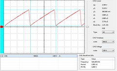
SC-01-A datasheet where they had RC set to 6.5k * 300pf in their reference circuits. After some experimentation; I determined that a 11kohm [Brown, Brown, Orange] (from 12V to the C22 cap) and the original C22 300pf cap would "clock" the speech chip and allow it to speak in test mode. Measuring the top of C22 in this config seemed to give me ~5V sawtooth waveform at ~530kHz.
I then removed the 11k resistor and adjusted R6 to ~530kHz. Why not 720kHz as described in the datasheet? Well; it appears my 20pf scope probes load the multivibrator enough to decrease timing by a significant margin. By adjusting to ~530kHz, the robotic voice sounded about right without the scope probe. Keep in mind that if you test with the scope probe attached; the voice will be slower than normal so do not adjust the R6 pot to proper speed with the probe attached.
I've documented this here so others can have a means to verify the clock circuit without replacing the entire section like I did.
Click Me to EnlargeHope this helps someone in the future.


