WPC Driver Board UpgradesThese are mandatory upgrades that SHOULD be done to any WPC machines. It is a relatively simple job if you have the correct tools. I do this to EVERY machine that needs to be worked on. Why do we need to do this upgrade ? Mainly because of the infamous "reset" on WPC machines - more to do with the combination of BR2 and C5 - the +5V. If this voltage fluctuates, so does the reliability of the game. Most of this procedure is covered in Clay's guides, but with my "guide" I have provided progress pictures. I replace all the Bridge Rectifiers and Capacitors.
The parts you need are simply ;
Bridge Rectifier - 400V 35A Wire legs, or 600V 35A Wire Legs
Capacitor - 15,000 mfd 25 Volt
Both are available locally from our Sponsors
http://www.rtbb.com.au/catalog/product_info.php?products_id=544http://www.rtbb.com.au/catalog/product_info.php?products_id=918If not in stock, GPE in the USA will have them, but support the local guys !
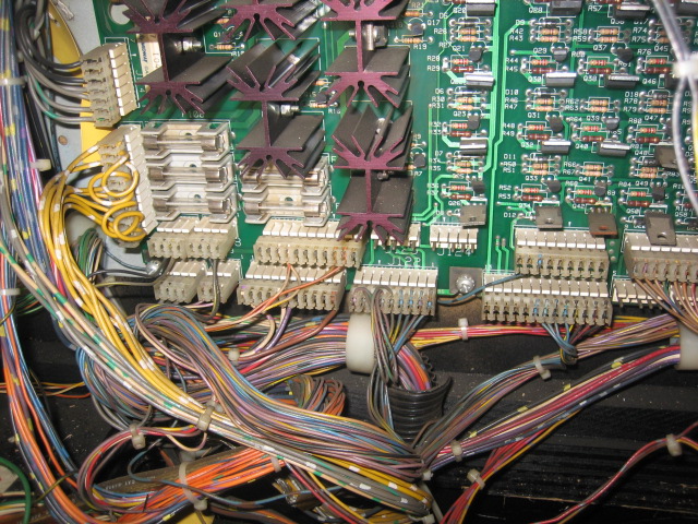
Before we start Removing the Driver board involves one key process - LABEL all connectors to the board - Either place a tag on the cable, or write directly on the connector. This will make it a lot easier to install when done ! Take note of the connectors - do any of them look burnt or hacked ? Check the bottom left hand corner - J120 and J121 - These are GI connectors and are almost ALWAYS toasted. This particular board is in excellent condition, so this is what you want to see ! The reason you need to take note is because you will have to replace the connectors, and it is easy to do that while the board is out to do the upgrades.
Here's the GI connectors - Not a good example of what to look for as this board is very good !
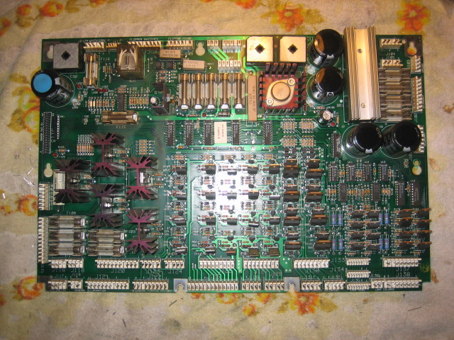
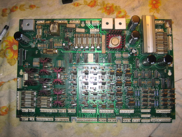
This is the Driver board once removed from the game !
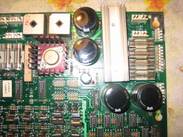
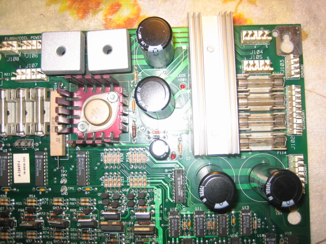
The main culprits - BR1, BR2, BR3, BR4, C11 and C5.
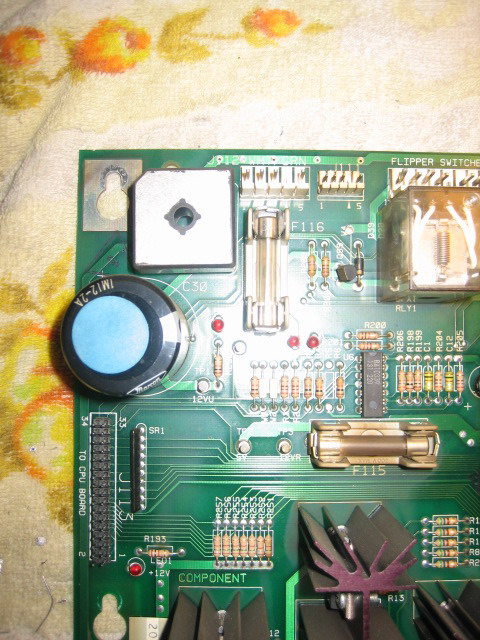
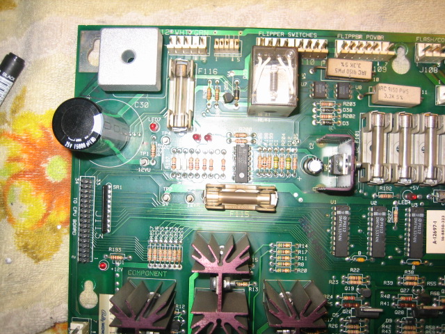
BR5 and C30
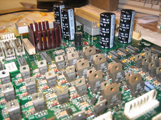
These 5 capacitors and 5 Bridge Rectifiers will be removed and replaced. I USED to use a standard soldering station and solder "sucker" - But this time around, I will be using my Desoldering station.
So this is where I get to test out my Aoyue 701. Removing the Caps and Bridge rectifiers is always a bit of a challenge, as the legs on the Caps are not the expected wire legs, they are more like lugs and they often remove the collar that is the conductor between one side of the board with the other. Sometimes, after completing these upgrades, some voltages may not be present. The Marvin's guide adds jumpers for this very reason, and I've always used them in the past.
I've preheated my desoldering gun, and I've used a little solder for the tip of the gun. The BRs were removed in around a minute per BR ! VERY easy - "stuff all" effort. They simply "fell off" the board once I have done the last of the four legs ! The Caps could not be removed with the desoldering gun - there needs to be a continuous heat applied to each leg. So I used the solder pencil. I placed a fresh "Ball" of solder on each leg and heated one leg up, then gently pulled the leg a little - moved to the opposite leg and did the same. so effectively, I heated up each leg and SLOWLY extracted the capacitor. Took time - but as I removed each Cap, I checked for the copper "collar" - none present - so I dropped a bit of solder on the pads of each removed Cap and used the desoldering gun to "clean up" the hole. This technique worked well - and I had all 5 caps and BRs out in around 15 minutes.
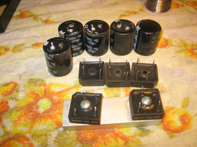
The old ;
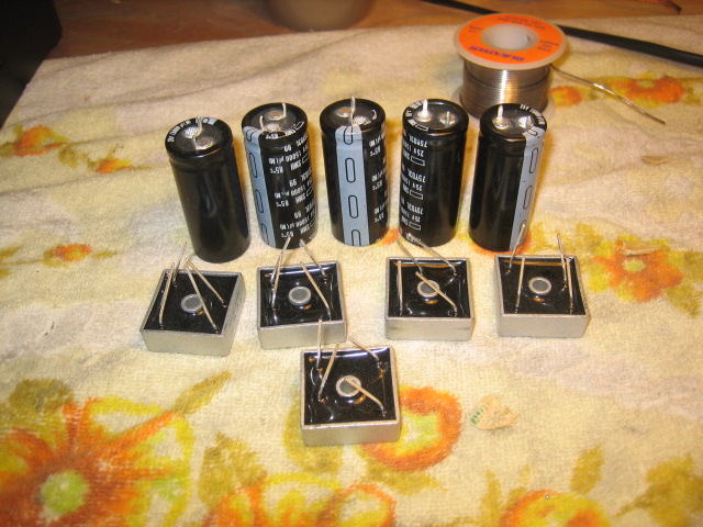
The new ;
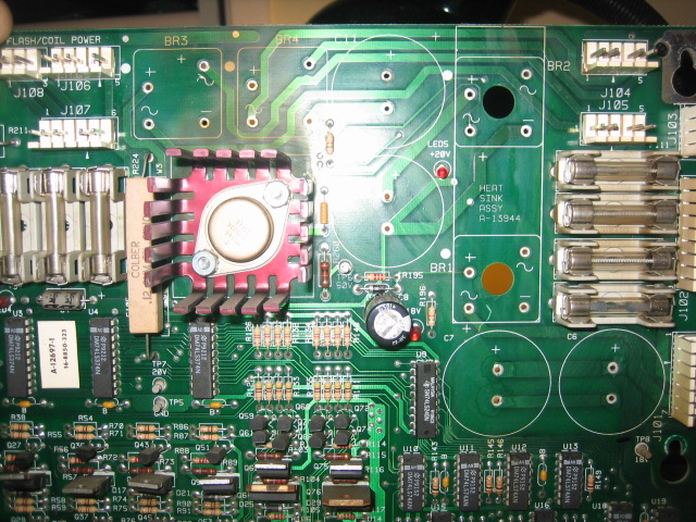
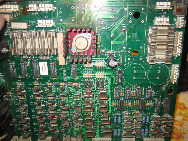
Here's some pictures of the board with the Caps and BRs removed. Very clean job (this time)
To install the new parts - start with the BRs. Make sure they are installed correctly. Now the really good thing about using a Desoldering Gun, is that the solder pads are clean and the holes have no solder - so when you resolder, the solder can pass through the hole and flow through the collar to the other side of the board. Leave plenty of room in between the BR and the board. Just in case when you solder - the solder does not make a good connection on BOTH SIDES of the board - this is important - especially if the collar was damaged (or any tracks), when the old parts were removed. Now check that the solder is on both sides of the board. If now - now is the time to use the space between the board and the BR to drop some solder on the parts side.
Now install the Caps - make sure they are pushed in all the way.
Should look something like this
Jumpers - I didn't really need them, but I've install some anyway on the main culprits. I mark them out with a permanent marker before taking the parts out. The aim is to ensure that the tracks on the parts side of the board are not severed IF the collars were damaged during removal. So what you do is check the tracks on the parts side while the caps and BRs are removed, and draw a line from the Caps two solder pads to their next component on the solder side. This is where the jumpers will be installed. They are usually connected to the corresponding BR.
Here's an example
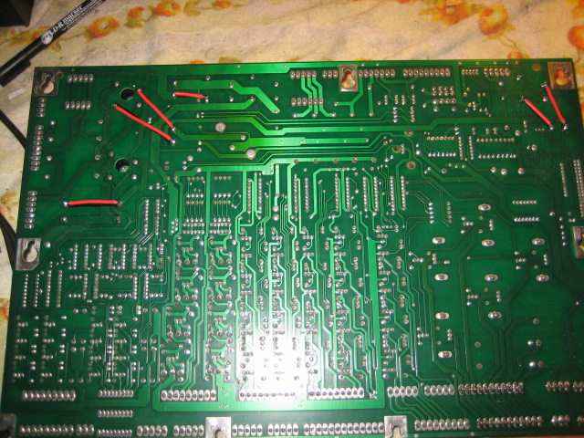
Hard to explain, but it is always advantageous to install the jumpers.
Now that I've used the Desoldering Station for this task - I'll NEVER go back ! While the board is out - Check the GI connectors J120 and J121. Reflow the solder - regardless of whether they look "good" !


