This procedure was covered on the Galaxy Restore Thread;
http://aussiepinball.com/index.php?topic=1256.0It is also documented here ;
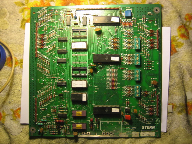
MPU Background and issuesThe MPU is a -200 MPU which is very similar to the Bally -35 board with the exception that the -200 has a second 5101 Chip and it runs at a higher clock speed. It is a VERY stable board, and has far less hassles if you want to upgrade the board to using 2732K Eproms to replace the original masked ROMS.
The problem with the original masked ROMs is that they are no longer available, and when they are damaged, the only real fix is to replace them with Eproms. 2716K or 2732K are the options. For the Galaxy MPU, it had an issue whereby the board would be "locked on" every 10 reboots. The problem is typical of these boards if the ROM sockets are bad, component failure (one of the ROMs, PIA or CPU) or corrosion from the battery around the reset section.
For this particular board, the masked ROMs had brittle legs. One of the legs on U1 ROM was broken after I attempted to clean it with sandpaper. The only option was to upgrade the ROMs. I downloaded the ROMs from the Internet Pinball Database and combined them into one binary file. Then I used my Willem Programmer to program the new ROMs on to 2732K Eproms. Then next step was to set the correct jumpers on the MPU to accommodate 2732K Eproms. According to Clay's guide, the jumpers should be set to ;
E1-E2
E4-E5
E13-E15
E24-E25
E16-E18
E32-E33
E34-E35
The process to convert the original board is simple. Record the current jumper configuration. If it is a factory configuration, then this is the procedure to convert the board for 2732K Eproms ;
Remove E2-E3
Solder E1-E2
Remove E5-E7
Solder E4-E5
Remove E8-E9
Remove E12-E13
Solder E13-E15
Remove E19-E20
Remove E22-E25
Solder E24-E25
Remove E26-E28
Remove E29-E31
This will give you a configuration for a combined U1 + U2 on a 2732K Eprom, installed in the U2 Socket, and a combined U5 + U6 on a 2732K Eprom, installed in the U6 Socket
Completing this process gave me a bootable -200 board with new 2732K Eproms at U2 and U6
The problem of the boot sequence locking up once every 10 boots is still a problem. A neat little test it to short out pins 39-40 on the CPU. This simulates a RESET of the CPU, which is the same as the RESET signal from the reset circuit. It worked every time, and the real test was to have the reset work at the CPU when the board was locked. Time to "bite the bullet" and replace the Reset Circuit with a Corrosion Kit from GPE. I've done PLENTY of these in the past, so they are easy - and it is time to document it.
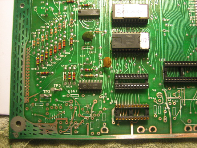
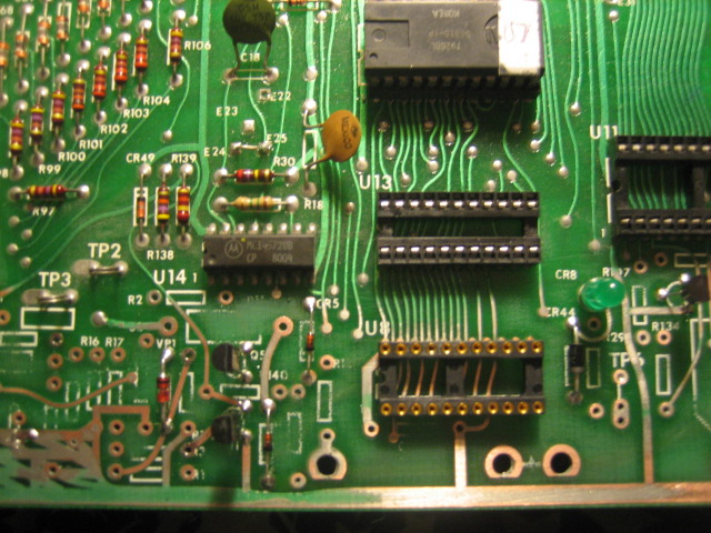
The MPU BoardHere's the Galaxy MPU board with the replacement Eproms installed. It boots 9/10 times. The battery is removed revealing only a small small amount of corrosion - but even the smallest amount can cause problems. I will be components in the reset section.
 The Reset Section
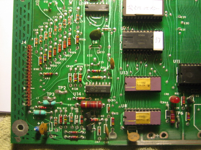
In the picture below, you can just see evidence of the corrosion. R1, R3, Q1 and Q5. These will be the culprits, but rather than replace them, I always replace all components in this "corrosion zone". You can also see sections like the base of R12 - this is the start of a potential problem. The damage has been done.
 CMOS RAM 5101
Rule of thumb - Wear a static wrist strap and use the correct tools to remove the 5101. DO NOT TOUCH THE LEGS. They are CMOS devices suseptible to static and they are easily damaged. I've done a few in the past. They are expensive and are fast becoming a rare part. Please be careful !
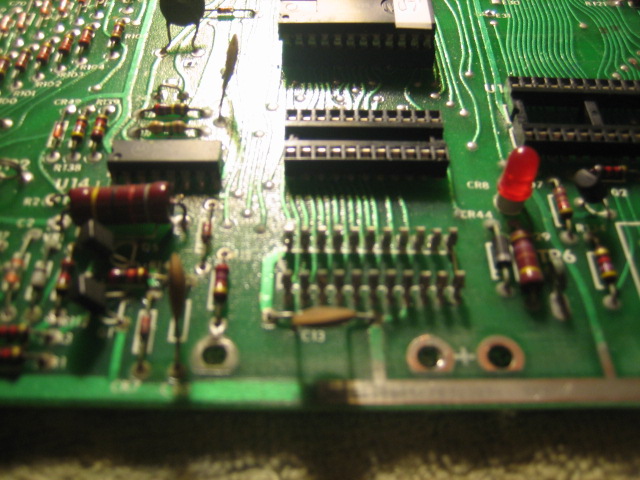
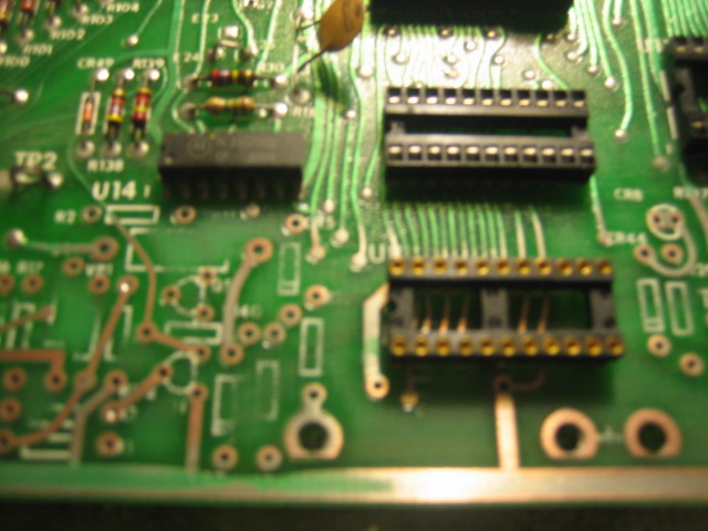
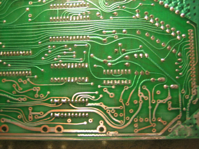
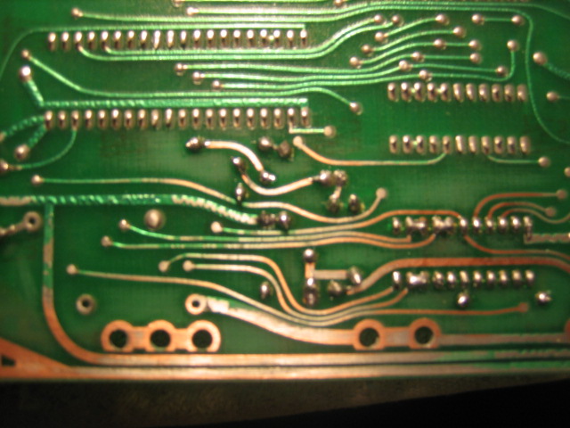
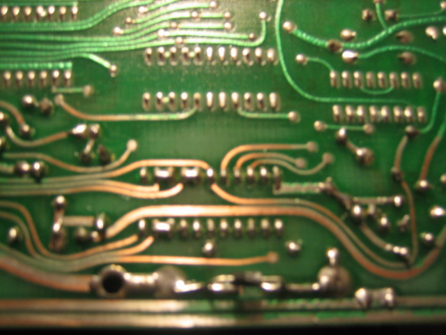
In the picture below I've removed the 5101 CMOS chips. I've prized the socket free of the board because I noticed some corrosion. The photo is not the greatest quality, but those pins ARE BADLY corroded. The clue was evident once the 5101 was removed. Even under the board, on the solder side, there was evidence of corrosion.
This is a poor picture - but it explains how to remove the legs without damaging the solder pads. Use a fine tipped soldering iron. Place the iron on the tip of the pin. Drop some solder on the iron / pin until you see the pin is moving free. GENTLY raise the pin out of the socket. You can use needle nose pliers. I use the iron because I've been using this technique for years on far worse boards.
All the components are removed by using a set of sidecutters to snip the components out of the board, and then using the fine tip on my iron with a manual solder sucker. I will be investing in a rework station soon.
Once all the components are removed, each hole needs to have the solder removed. Not too much heat. If they are stubborn and the solder won't heat up, then grab some 360 Grit sandpaper and sand off the corrosion to reveal the solder. Then remove the solder. Once this is all done, use 360 Grit to completely remove any old solder and remnants of corrosion. Grab a toothbrush and solution of 50/50 water and vinegar to neutralize the corrosion. Then wash the area with alcohol.
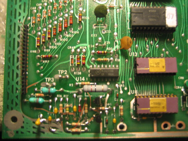
In the pictures below, I've already done this part of the repair, and installed the socket for the lower 5101.
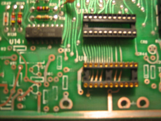
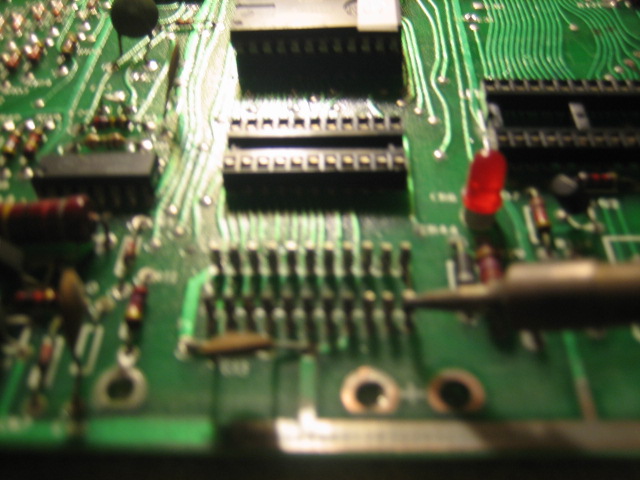
Next we install the transistors, LED and Diodes. Notice I solder the top of the solder pads and the bottom. I Leave the components slightly raised so I can access the legs with a soldering iron.
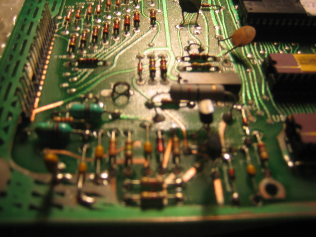
Next are the Capacitors and Resistors. I reuse the inductors, as long as they are not affected by the corrosion, and I always replace J$ as the corrosion finds itself under the connector, causing all sorts of issues.
 Battery Replacement
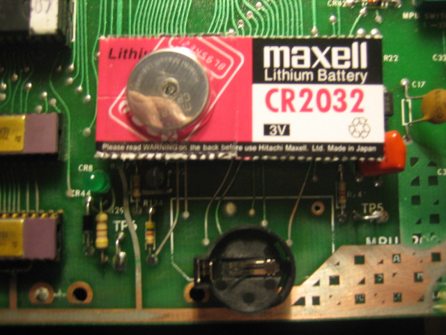
A cheap way of replacing the battery is to install a Lithium Calculator Battery. This solution was described to me by Skybeaux (Ken) a while ago, after he commented on my previous method of installing expensive memory capacitors. This is also an easier method
The holders are available from any electronics store ;
It solders straight onto the board
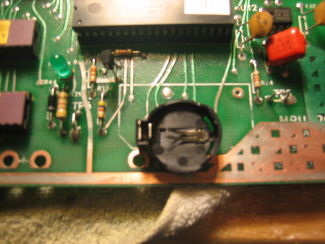
Just above the cavity for the old Battery - you just need to solder a jumper from the left hand solder pad, to the three holes (jumper not pictured)
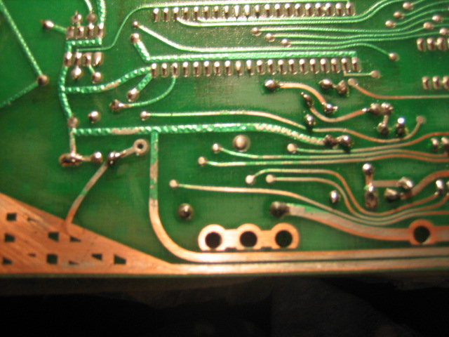
Cut the trace between the old battery holes, and solder in a blocking diode (1n4007 will do). Install the battery and you are done !
Test the board on the test rig and it runs perfectly. I'll add to this thread when the board is mounted with new connectors etc..


