Author Topic: Bally Solenoid Driver Repair  (Read 12849 times)

0 Members and 1 Guest are viewing this topic.

Offline Strangeways

  • Pinball Restoration is my passion
  • Administrator
  • Trade Count: (+9)
  • *****
  • High Score Initials:
  • Forum Posts:
  • Melbourne
  • ABN 68 283 634 461
    • Ride The Boney Beast
Bally Solenoid Driver Repair
« on: October 17, 2008, 06:08:42 PM »

Here's something a little different. I'm going to start logging repairs on various boards I have lying around that need repairs. I'm mainly going to focus on games and boards I have a lot of experience with, and some repair techniques that I've used over the years.

Solenoid Driver (Bally / Stern 1977 - 1981)

This board is typical of the boards that have never been repaired or reconditioned. This is a very important component of the Pinballs of this era and if they are not attended to, they can damage OTHER components of your game - particularly displays.

The problems with this board are not visibly noticeable, and you probably would not know there is a problem until you tested it. I plays fine in my Paragon... But there are several issues with this board....


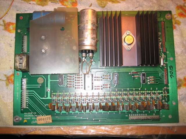
Look at the large silver capacitor.. That's a factory cap that was designed for 10 years operation.
Look at the large blue capacitor.. again ..That's a factory cap that was designed for 10 years operation, and it is leaking !

Measure TP2 and TP4 to ground... Hmmm.. Both over 200 VDC. This is a HUUUGE problem...The HV to the displays is no longer regulating, and I cannot adjust the pot to lower the voltage to 175 - 185 VDC...

But The boards works ???

It is actually DAMAGING the displays, and if you had an Altec MPU board in the game... That could be nasty...


Aussie Pinball - Proud to be Australia's Premier Pinball Forum

http://www.australianpinballrestorations.com.au/

http://www.rtbb.com.au/catalog/

We carry the largest range of NEW Ramps in Australia

Offline Creech

  • Forum Founder
  • Trade Count: (0)
  • *****
  • Forum Posts:
  • Adelaide
Re: Bally Solenoid Driver Repair
« Reply #1 on: October 17, 2008, 07:16:50 PM »
So what do you do next on this board? Just replace the caps? Very interested to see what you do here.

Offline Ballywannabe

  • Trade Count: (0)
  • *****
  • Forum Posts:
  • Perth
Re: Bally Solenoid Driver Repair
« Reply #2 on: October 17, 2008, 09:39:23 PM »
Here is what I would do - replace both Caps, rebuild the HV section, create a stronger ground for both caps, tie TP1 with TP3, replace j3 header pins and make a nice new plastic HV section cover.  Can't see the back but I would check for burning on the flipper relay tracks and put in additional jumpers if they look toasty, as well as tidying up any previous hacks.  Lets see how close I am!

cheers
Ian

Offline Creech

  • Forum Founder
  • Trade Count: (0)
  • *****
  • Forum Posts:
  • Adelaide
Re: Bally Solenoid Driver Repair
« Reply #3 on: October 17, 2008, 10:17:33 PM »
Where do you guys learn all this stuff? I'm amazed. Does Clay's guide have all this stuff?

stuba

  • Guest
  • Trade Count: (0)
Re: Bally Solenoid Driver Repair
« Reply #4 on: October 17, 2008, 10:18:27 PM »
funny spotting this thread. i have just finished soldering today on the HV section of a -22 SDB board for an EBD. TP2 and TP4 were both testing at 240+ and as per clays guide  - > rebuild time. Note that C23 is for the 5v section. I washed down the board with a 50/50 vinegar/water solution and fired up the desolderer. I used a bigdaddy enterprises kit. still got to do the regulator as i got interupted and then need to buzz out to make sure connections are good (couple of traces are jumpered). Ed at GPE also sells a HV kit. I also replaced a couple of the TIP102's. Query - I used diode MM test on the TIPS and when in circuit they test 45/49 - is this about right?? out of circuit is closer to 45/60 (grounding centre pin). will test the board in machi9ne tommorrow.


Offline Strangeways

  • Pinball Restoration is my passion
  • Administrator
  • Trade Count: (+9)
  • *****
  • High Score Initials:
  • Forum Posts:
  • Melbourne
  • ABN 68 283 634 461
    • Ride The Boney Beast
Re: Bally Solenoid Driver Repair
« Reply #5 on: October 17, 2008, 10:56:04 PM »
Here is what I would do - replace both Caps, rebuild the HV section, create a stronger ground for both caps, tie TP1 with TP3, replace j3 header pins and make a nice new plastic HV section cover.  Can't see the back but I would check for burning on the flipper relay tracks and put in additional jumpers if they look toasty, as well as tidying up any previous hacks.  Lets see how close I am!

cheers
Ian

Well done Ian  #*#

There are a few extra steps that I do - I made my own HV rebuild kit - an addition to Ed's HV rebuild kit..

I'll document the process as I go along..I'm glad to see that there is an interest in board repairs and upgrades


Aussie Pinball - Proud to be Australia's Premier Pinball Forum

http://www.australianpinballrestorations.com.au/

http://www.rtbb.com.au/catalog/

We carry the largest range of NEW Ramps in Australia

Offline Strangeways

  • Pinball Restoration is my passion
  • Administrator
  • Trade Count: (+9)
  • *****
  • High Score Initials:
  • Forum Posts:
  • Melbourne
  • ABN 68 283 634 461
    • Ride The Boney Beast
Re: Bally Solenoid Driver Repair
« Reply #6 on: October 17, 2008, 11:03:57 PM »
Where do you guys learn all this stuff? I'm amazed. Does Clay's guide have all this stuff?

Yes - Clay documents troubleshooting this board and the mandatory upgrades.. Clay has been an inspiration to pinheads like myself to get involved with these repairs.

I have been doing board repairs for many years now, and it is not as difficult as it looks. I do have an Electronics background, so it does make it easier.

I guess it would be the responsible thing to alert pinheads that the repair knowledge I want to share is based on experience. I have made many mistakes and that's the best way to learn. Electronics and Electricity are not forgiving, so take care if you want to try this yourself.

 ^^^
Aussie Pinball - Proud to be Australia's Premier Pinball Forum

http://www.australianpinballrestorations.com.au/

http://www.rtbb.com.au/catalog/

We carry the largest range of NEW Ramps in Australia

Offline Ballywannabe

  • Trade Count: (0)
  • *****
  • Forum Posts:
  • Perth
Re: Bally Solenoid Driver Repair
« Reply #7 on: October 18, 2008, 12:27:49 AM »
Where do you guys learn all this stuff? I'm amazed. Does Clay's guide have all this stuff?

Yes - Clay documents troubleshooting this board and the mandatory upgrades.. Clay has been an inspiration to pinheads like myself to get involved with these repairs.

I have been doing board repairs for many years now, and it is not as difficult as it looks. I do have an Electronics background, so it does make it easier.

I guess it would be the responsible thing to alert pinheads that the repair knowledge I want to share is based on experience. I have made many mistakes and that's the best way to learn. Electronics and Electricity are not forgiving, so take care if you want to try this yourself.

 ^^^

Right on.  Clay's guides mean that if you have fair to good electronic skills you can use the guide to make a lot of board repairs yourself.  Without the guide I would be struggling...

Offline Ballywannabe

  • Trade Count: (0)
  • *****
  • Forum Posts:
  • Perth
Re: Bally Solenoid Driver Repair
« Reply #8 on: October 18, 2008, 12:34:03 AM »
I also replaced a couple of the TIP102's. Query - I used diode MM test on the TIPS and when in circuit they test 45/49 - is this about right?? out of circuit is closer to 45/60 (grounding centre pin). will test the board in machi9ne tommorrow.

I don't have a huge success rate testing with a meter, and often rely on the 'in machine' test.  If it works in the machine I would not worry about it.  Keep in mind that it is not always the TIP that plays up, and the CA3081 (transistor pack) can also go open and cause a coil to lock on.  If you have a problem (coil locked on or won't fire) check the schematics and then test ALL the components that fire that coil.

cheers
Ian

Offline Pinball Fixers

  • Trade Count: (0)
  • ******
  • Forum Posts:
  • Montrose, VIC
Re: Bally Solenoid Driver Repair
« Reply #9 on: October 18, 2008, 01:02:44 AM »
Seeing as you have started this thread Nino, I will chime in (in new threads) with the various faults and solutions I have had over the years with different pinball circuit boards.

This will be a great resource for anyone who has soldering skills to do this sort of work...

stuba

  • Guest
  • Trade Count: (0)
Re: Bally Solenoid Driver Repair
« Reply #10 on: October 18, 2008, 09:33:18 AM »
righto then. at the risk of being pushy I do have the board out at the moment (first time I've done one of these boards which is why I'm asking). i have rebuilt ALL of the HV components, looks like one of the 1/2 watt resistors cooked a while back (before the replaced upgrade). i'll do the ground upgrades on the 2 big caps and tie TP1 and TP3. i will do the headers and connectors, I am upgrading C23 to 15K mf (EBD has 3 flippers). I have a replacement flipper relay but wasn't going to replace it because the other one is working fine (should I ?) - are these a common cause of failure? appreciate your comments guys if there is anything else you recommend! cheers s

to any noobs reading this thread, have a go!, it's pretty satisfying to be able to fix your game from top to bottom. if you haven't done much/any soldering do an online tutorial and maybe practice on a cheap jaycar kit or something before tackling a pin board. the one main thing i have learned is you should spend more care and time on component removal than component addition. Those traces are hard to repair if you carelessly break them removing components (get a good pair of tiny sidecutters and take no risks 'pulling' components - cut them off!). also 'test' your work with a MM before connecting the power! test for shorts if it looks like a couple of joints may be too close and make sure your connections are tight.


Offline silverball

  • Trade Count: (0)
  • ******
  • Forum Posts:
Re: Bally Solenoid Driver Repair
« Reply #11 on: October 18, 2008, 10:30:19 AM »
Reading this thread with a system 11 power board in front of me, another coincidence. +100v is ok -100v reads -130v and is like nino mentioned, affecting the display. Just began testing last night. Havent played much with sys 11's but learning my way around quick. Anyone point the finger at the above culprit before I test all components? Thinking it may be a cap.

Offline Mr Pinbologist

  • Trade Count: (+5)
  • ******
  • High Score Initials:
  • Forum Posts:
  • Wauchope NSW
Re: Bally Solenoid Driver Repair
« Reply #12 on: October 18, 2008, 10:57:18 AM »
Where do you guys learn all this stuff? I'm amazed. Does Clay's guide have all this stuff?

Yes - Clay documents troubleshooting this board and the mandatory upgrades.. Clay has been an inspiration to pinheads like myself to get involved with these repairs.

I have been doing board repairs for many years now, and it is not as difficult as it looks. I do have an Electronics background, so it does make it easier.

I guess it would be the responsible thing to alert pinheads that the repair knowledge I want to share is based on experience. I have made many mistakes and that's the best way to learn. Electronics and Electricity are not forgiving, so take care if you want to try this yourself.

 ^^^


Good Advice. ^^^ Im glad to see this kind of advice, especially regarding high voltages. Im an electronics tech by trade and work with dangerous voltages every day of my life.. plasma tv's, microwave ovens etc, and im all to familiar with how dangerous electricity can be through bitter experience. Ten years ago I ended up in hospital once with burns all over my right hand and will have the scars for the rest of my life.. due to being careless and complacant. But i was VERY lucky.. the path of the electricity went in and came out thru ny right hand, had it exited thru my left hand i would not be writing this now... So please be careful.. id hate to read on here about someone having any kind of accident while working on one of their beloved games


Offline Strangeways

  • Pinball Restoration is my passion
  • Administrator
  • Trade Count: (+9)
  • *****
  • High Score Initials:
  • Forum Posts:
  • Melbourne
  • ABN 68 283 634 461
    • Ride The Boney Beast
Re: Bally Solenoid Driver Repair
« Reply #13 on: October 18, 2008, 11:05:13 AM »
righto then. at the risk of being pushy I do have the board out at the moment (first time I've done one of these boards which is why I'm asking). i have rebuilt ALL of the HV components, looks like one of the 1/2 watt resistors cooked a while back (before the replaced upgrade). i'll do the ground upgrades on the 2 big caps and tie TP1 and TP3. i will do the headers and connectors, I am upgrading C23 to 15K mf (EBD has 3 flippers). I have a replacement flipper relay but wasn't going to replace it because the other one is working fine (should I ?) - are these a common cause of failure? appreciate your comments guys if there is anything else you recommend! cheers s

to any noobs reading this thread, have a go!, it's pretty satisfying to be able to fix your game from top to bottom. if you haven't done much/any soldering do an online tutorial and maybe practice on a cheap jaycar kit or something before tackling a pin board. the one main thing i have learned is you should spend more care and time on component removal than component addition. Those traces are hard to repair if you carelessly break them removing components (get a good pair of tiny sidecutters and take no risks 'pulling' components - cut them off!). also 'test' your work with a MM before connecting the power! test for shorts if it looks like a couple of joints may be too close and make sure your connections are tight.


You should be right Stu. The best way to check a TIP102 is to set the MM to "continuity" and then check for any shorts. Testing them this way is the easiest, and when you switch the game on, you won't have any locked on coils caused by the transistors. Measuring resistance to ground will give you different readings as you are measuring the "circuit", not the component. There are other components influencing the reading as the other components can have a 10% tolerance - like resistors for example..


Aussie Pinball - Proud to be Australia's Premier Pinball Forum

http://www.australianpinballrestorations.com.au/

http://www.rtbb.com.au/catalog/

We carry the largest range of NEW Ramps in Australia

Offline Strangeways

  • Pinball Restoration is my passion
  • Administrator
  • Trade Count: (+9)
  • *****
  • High Score Initials:
  • Forum Posts:
  • Melbourne
  • ABN 68 283 634 461
    • Ride The Boney Beast
Re: Bally Solenoid Driver Repair
« Reply #14 on: October 18, 2008, 11:05:50 AM »
Seeing as you have started this thread Nino, I will chime in (in new threads) with the various faults and solutions I have had over the years with different pinball circuit boards.

This will be a great resource for anyone who has soldering skills to do this sort of work...

I was hoping you would do that, Owen  ^^^
Aussie Pinball - Proud to be Australia's Premier Pinball Forum

http://www.australianpinballrestorations.com.au/

http://www.rtbb.com.au/catalog/

We carry the largest range of NEW Ramps in Australia